
Fluid refractive index optimizing particle counter

a technology of refractive index and particle counter, which is applied in the field of fluid refractive index optimizing particle counter, can solve the problems of reducing or eliminating the efficacy of particle detectors, affecting the accuracy of particle detection, and increasing the complexity of optical components to detect particles

Active Publication Date: 2022-05-03
PARTICLE MEASURING SYST
View PDF84 Cites 2 Cited by
  • Summary
  • Abstract
  • Description
  • Claims
  • Application Information

AI Technical Summary

Benefits of technology

The patent describes optical particle analyzers and counters that can account for the refractive index of the fluid in which particles are flowed. This is important because it allows the analyzer to accurately detect and characterize smaller particles. The refractive index optimizer can adjust the optical components to optimize the collection of scattered or emitted electromagnetic radiation from the particles. This results in increased sensitivity and accuracy of the particle analyzer. The analyzers can be used in various applications and can be positioned and adjusted based on the refractive index of the fluid. The method can also include measuring the refractive index of the fluid and adjusting the position of the laser or optical collection system accordingly to maximize the signal output of the optical particle counter.

Problems solved by technology

As particle size decreases, the complexity of the optical components to detect the particles increases dramatically.
However, many industries use a variety of different fluids within their cleanroom or controlled environments and a change in refractive index of the fluid being analyzed may reduce or eliminate the efficacy of the particle detector because the change in refractive index alters the path of the electromagnetic radiation as it passes through the flow cell.
The change in path alters the ideal point of measurement (focal point) for the collection and / or detection system analyzing the electromagnetic radiation and may no longer be able to provide accurate characterization of the particles passing through the flow cell.
Calibration is time consuming, expensive and requires taking the particle counter offline.

Method used


Image

  • Fluid refractive index optimizing particle counter
  • Fluid refractive index optimizing particle counter
  • Fluid refractive index optimizing particle counter

Examples


example 1

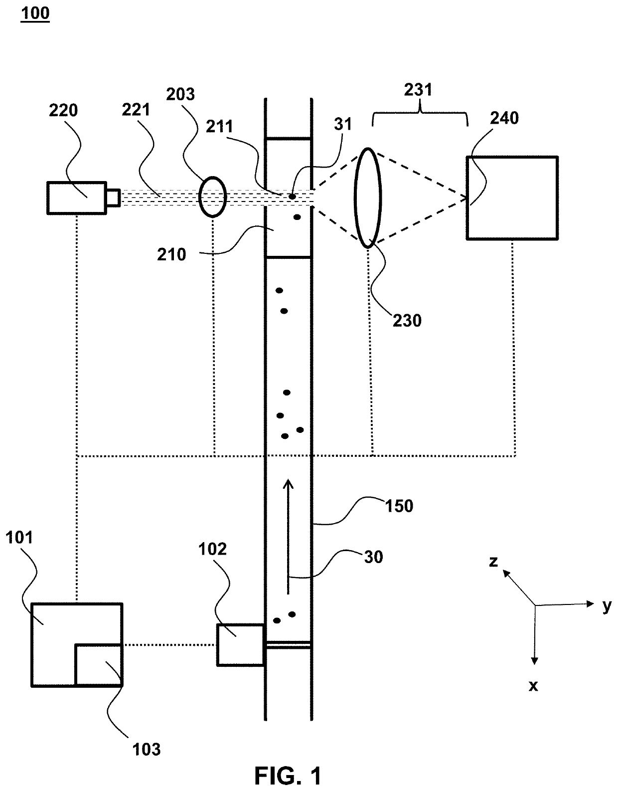
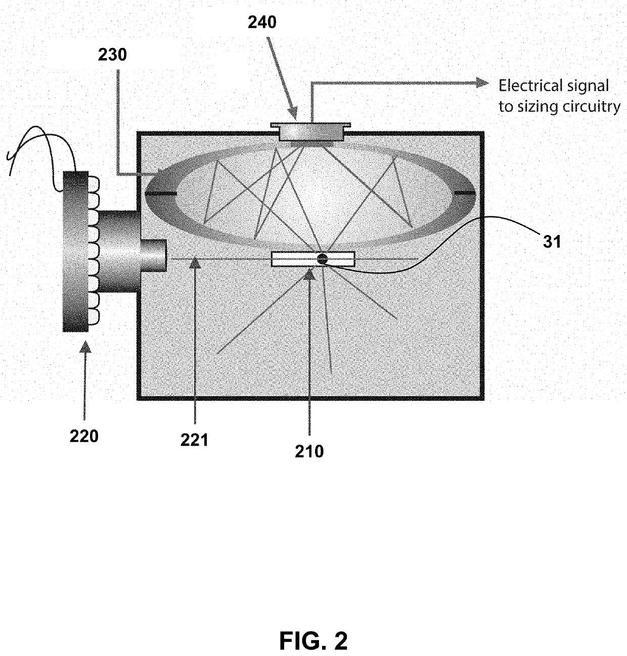
[0046]This example demonstrates an optical particle counter including a refractive index optimizer that adjusts various aspects of the system (e.g. component positioning, beam properties) to ensure the focal point of the system is positioned within tolerance and the data being generated is accurate. In these systems, the refractive index optimizer is an active design element to ensure electromagnetic radiation is collected, then focused or magnified onto the detector from the ideal point of measure in the sample or flow cell.

[0047]Fluid refractive index variances cause a shift in the optical system focal point within the measurement cell which can impact the beam shape and position as well as the region within the cell from which light is collected and properly focused on the detector. Individually, or in combination, these variances can impact the performance of the particle counter in several ways.

[0048]An integrated refractive index optimizer and optical particle counter is provi...


PUM

PropertyMeasurementUnit
refractive indexaaaaaaaaaa
particle sizeaaaaaaaaaa
wavelengthsaaaaaaaaaa

Abstract

Provided herein are systems and methods of optical particle counters which account and adjust for the refractive index of the carrier fluid being analyzed. The provided systems are robust and may be implemented in a variety of optical particle counters including obscured light, reflected light, emitted light and scattered light particle counters. The described systems may be useful with any fluid, including gases or liquids. In some cases, the system can account for the differences in refractive index between two liquids, for example, ultrapure water and an acid, such as sulfuric, hydrochloric, hydrofluoric, acetic, phosphoric, chromic phosphoric, and the like. By accounting for the refractive index of the carrier fluid, the described systems and methods are also more sensitive and able to more accurately detect and characterize smaller particles, including nanoscale sized particles.

Description

CROSS REFERENCE TO RELATED APPLICATIONS[0001]This application claims the benefit of priority to U.S. Provisional Patent Application No. 62 / 725,777 filed Aug. 31, 2018, which is incorporated herein by reference in its entirety to the extent not inconsistent herewith.BACKGROUND OF THE INVENTION[0002]Particle counters play a key role in modern manufacturing techniques as they monitor the environment for micro- and nano-scale particles that are problematic for a variety of industries including semiconductor fabrication and pharmaceutical or biotechnology production. As manufacturing processes have advanced, the need for the detection, characterization or removal of smaller and smaller particles is necessary.[0003]One common type of particle counter is an optical particle counter. These counters monitor a fluid stream and characterize particles therein by projecting electromagnetic radiation (typically via a laser) into a flow cell. The electromagnetic radiation interacts (scatters, refl...

Claims


Application Information

Patent Timeline
Patent Type & Authority Patents(United States)
IPC IPC(8): G01N15/14
CPCG01N15/1434G01N15/1425G01N2015/1452G01N2015/1486G01N15/1459G01N2015/0046
Inventor LUMPKIN, JAMES M.KNOLLENBERG, BRIAN A.MITCHELL, JOHN R.
Owner PARTICLE MEASURING SYST
Learn More