
Inkjet printer and control method for inkjet printer

a control method and printer technology, applied in the field of inkjet printers, can solve the problems of limited print conditions that can ensure the print quality of the print medium, and achieve the effects of ensuring the print quality of the print medium, and widening the range of print conditions

Active Publication Date: 2022-05-03
MIMAKI ENG
View PDF2 Cites 0 Cited by
  • Summary
  • Abstract
  • Description
  • Claims
  • Application Information

AI Technical Summary

Benefits of technology

The present patent relates to an inkjet printer that can print in a gloss tone printing mode. The patent addresses the issue of ensuring good print quality even with different print conditions. The invention provides a solution by controlling the average illuminance of the ultraviolet rays that cure the color ink after it has landed on the print medium. By doing so, the invention allows for main-curing of the color ink before printing the clear ink, which expands the range of print conditions that can achieve good print quality.

Problems solved by technology

Therefore, according to the study of the inventor of the present application, when the color ink is printed on the print medium and the clear ink is printed on the printed color ink in a gloss tone while moving the carriage in the main scanning direction, the print conditions that can ensure the print quality of the print medium are limited.
In addition, if the number of passes when performing printing on the print medium through the multi-pass method decreases, the cumulative light quantity cannot be secured only by controlling the leakage light from the fifth irradiation portion, and although the quality of blank character printing by clear ink cannot be ensured, with this configuration, the second irradiation portion makes it possible to secure the irradiation light quantity and to irradiate the entire surface with uniform ultraviolet rays.

Method used


Image

  • Inkjet printer and control method for inkjet printer
  • Inkjet printer and control method for inkjet printer
  • Inkjet printer and control method for inkjet printer

Examples


Embodiment Construction

[0036]Hereinafter, an embodiment of the present disclosure will be described with reference to the drawings.

[0037](Configuration of Inkjet Printer)

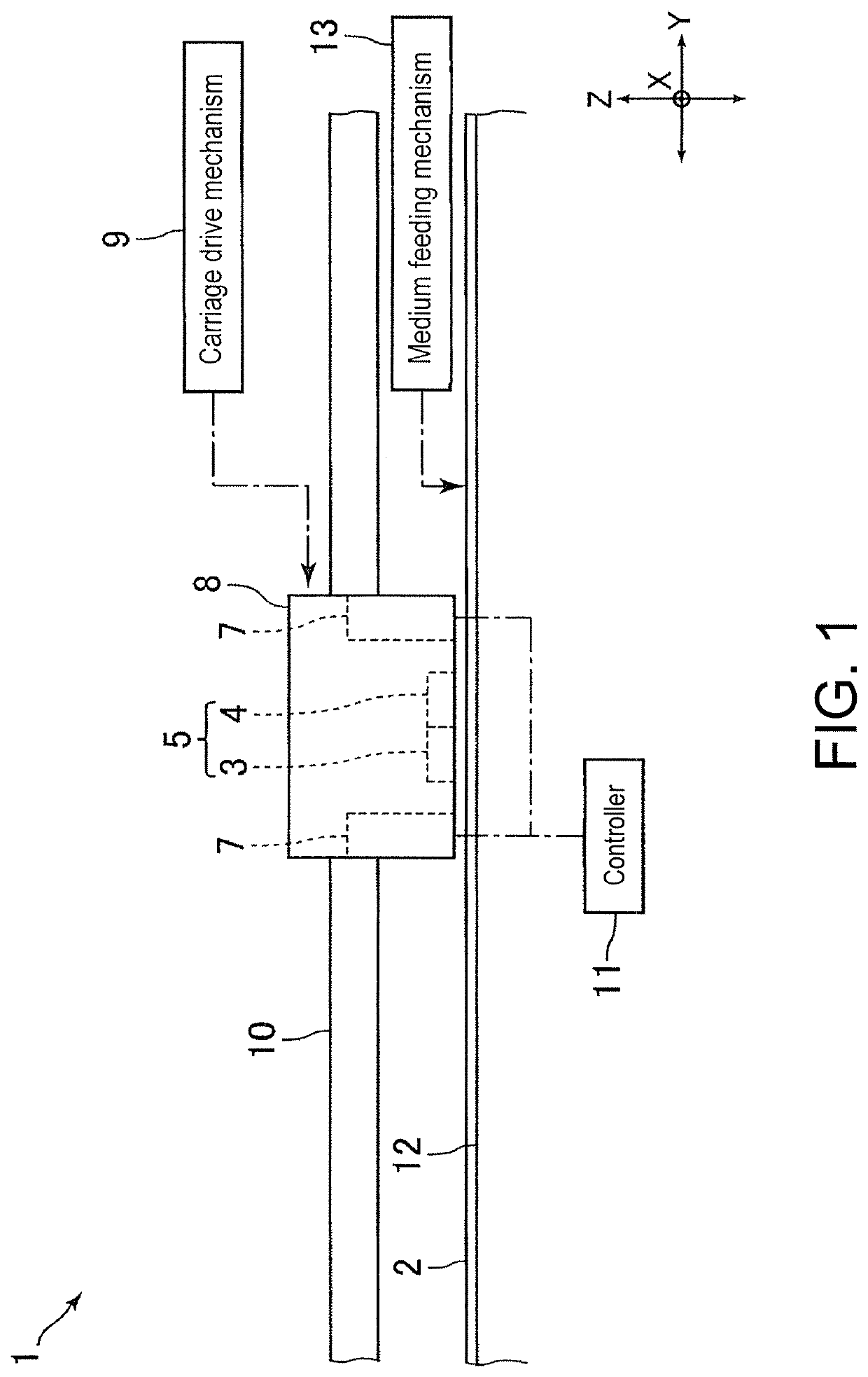
[0038]FIG. 1 is a schematic view for describing a configuration of an inkjet printer 1 according to an embodiment of the present disclosure. FIG. 2 is a bottom view for describing configurations of inkjet heads 3 and 4 and an ultraviolet irradiator 7 shown in FIG. 1. FIG. 3 is a view for describing an example of a value of current supplied to the ultraviolet irradiator 7 when performing printing on a print medium 2 in a gloss tone printing mode by the inkjet printer 1 shown in FIG. 1.

[0039]The inkjet printer 1 (hereinafter referred to as “printer 1”) of the present embodiment is a business inkjet printer, and performs printing on a print medium 2. The print medium 2 is printing paper, fabric, resin film, or the like. The printer 1 includes an inkjet head 3 (hereinafter referred to as “head 3”) and an inkjet head 4 (hereinafter referred to...


PUM

PropertyMeasurementUnit
currentaaaaaaaaaa
currentaaaaaaaaaa
currentaaaaaaaaaa

Abstract

In an inkjet printer, an ultraviolet irradiator includes a first irradiation portion disposed at the same position as a color ink ejection portion in a front-back direction and a third irradiation portion disposed on the front side of a clear ink ejection portion in the front-back direction, where at the time of printing in a gloss tone printing mode, an average illuminance of a fifth irradiation portion that forms the front side portion of the first irradiation portion is lower than an average illuminance of a fourth irradiation portion that forms the back side portion of the first irradiation portion.

Description

CROSS REFERENCE TO RELATED APPLICATIONS[0001]This application claims the priority benefit of Japanese Patent Application No. 2020-006475, filed on Jan. 20, 2020. The entirety of the above-mentioned patent application is hereby incorporated by reference herein and made a part of this specification.TECHNICAL FIELD[0002]The present disclosure relates to an inkjet printer that performs printing on a print medium by ejecting ultraviolet-curable ink. The present disclosure also relates to a control method for such an inkjet printer.DESCRIPTION OF THE BACKGROUND ART[0003]An inkjet printer that performs printing through a multi-pass method on a print medium is conventionally known (see e.g., Japanese Unexamined Patent Publication No. 2015-214133, i.e., Patent Literature 1). The inkjet printer described in Japanese Unexamined Patent Publication No. 2015-214133 has a head portion that ejects ink to a print medium, a carriage on which the head portion is mounted, and a scanning driving portion...

Claims


Application Information

Patent Timeline
Patent Type & Authority Patents(United States)
IPC IPC(8): B41J11/00
CPCB41J11/00214B41J11/00212B41J2/01B41J11/002B41J29/393B41J2/2114
Inventor KISHIDA, YUTARO
Owner MIMAKI ENG
Learn More