
Honeycomb structure

Active Publication Date: 2022-04-26
NGK INSULATORS LTD
View PDF12 Cites 0 Cited by
  • Summary
  • Abstract
  • Description
  • Claims
  • Application Information

AI Technical Summary

Benefits of technology

The present invention aims to provide a honeycomb structure that can effectively prevent cracks caused by burning and removing particles during electrical heating. The invention suppresses the generation of cracks and facilitates electrical control, allowing for efficient burning and removal of particles.

Problems solved by technology

When burning and removing particulates deposited in a honeycomb structure by electrically heating the honeycomb structure as a filter, combustion of the particulates on an inlet side of the honeycomb structure transmits combustion heat to a downstream side, so that a larger temperature difference is generated in a length direction of the honeycomb structure portion in conjunction with the combustion of the particulates on the downstream side, and cracks may be generated due to thermal stress.

Method used


Image

  • Honeycomb structure
  • Honeycomb structure
  • Honeycomb structure

Examples


examples

[0067]Hereinafter, Examples is illustrated for better understanding of the present invention and its advantages, but the present invention is not limited to these Examples.

[0068]Silicon carbide (SiC) powder and metallic silicon (Si) powder were mixed in a mass ratio of 60:40 to prepare a ceramic raw material. To the ceramic raw material were added hydroxypropyl methyl cellulose as a binder, a water absorbing resin as a pore former, and water to form a forming raw material. The forming raw material was then kneaded by means of a vacuum green body kneader to prepare a circular pillar shaped green body. The content of the binder was 7 parts by mass when the total of the silicon carbide powder (SiC) and the metallic silicon (Si) powder was 100 parts by mass. The content of the pore former was 3 parts by mass when the total of the silicon carbide powder (SiC) and the metallic silicon (Si) powder was 100 parts by mass. The content of water was 42 parts by mass when the total of the silico...


PUM

PropertyMeasurementUnit
Volumeaaaaaaaaaa
Lengthaaaaaaaaaa
Temperature coefficient of refractive indexaaaaaaaaaa

Abstract

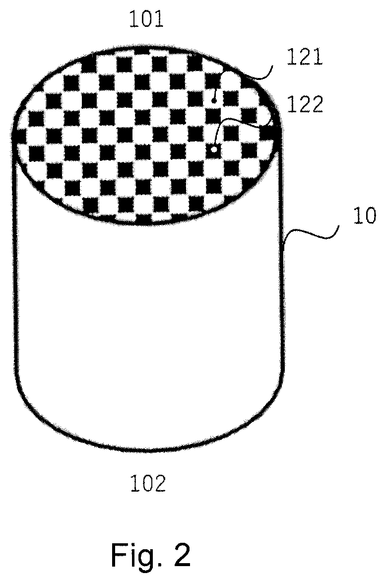
A honeycomb structure including a honeycomb portion having porous partition walls extending from an inflow end face to an outflow end face, an outermost peripheral wall, and a pair of electrode layers on a side surface of the honeycomb portion. Each electrode layer extends in a direction of the cells. One electrode layer is disposed on a side opposite to the other electrode layer across a center of the honeycomb portion in a cross section orthogonal to the extending direction of the cells. The honeycomb structure portion includes first cells opened on the inflow side and plugged on the outflow side, and second cells opened on the outflow side and plugged on the inflow side. A middle of each length of the pair of electrode layers is closer to the outflow side than a middle position of a length of the honeycomb portion in the extending direction of the cells.

Description

[0001]This application claims the benefit under 35 USC § 119(a)-(d) of Japanese Application No. 2018-065741 filed Mar. 29, 2018, the entirety of which is incorporated herein by reference.FIELD OF THE INVENTION[0002]The present invention relates to a honeycomb structure. More particularly, it relates to a honeycomb structure capable of effectively suppressing generation of cracks in a honeycomb structure due to combustion of particulates during electrical heating.BACKGROUND OF THE INVENTION[0003]Ceramic honeycomb structure filters are known for reducing particulates contained in motor vehicle exhaust gases. Further, a technique has been proposed in which a ceramic honeycomb filter itself is regarded as an electrical heating element, and particulates are burned off by electrical heating.[0004]Patent Document 1 discloses a filter device for removing flammable particulates, the filter comprising a wall structure that forms a plurality of paths each extending from an inlet side to an out...

Claims


Application Information

Patent Timeline
IPC IPC(8): B01D46/24C04B38/00B01D39/20B01D46/00C04B35/565
CPCC04B38/0009B01D39/2068B01D46/0063B01D46/2418B01D46/2429B01D46/2474C04B35/565B01D46/2486B01D46/24491B01D46/0002B01D46/2482B01D46/2476C04B2235/3826C04B2235/428C04B35/6263C04B2235/5436C04B2235/606C04B2235/663B01D46/84
Inventor KASAI, YOSHIYUKISHIBAGAKI, YUKINARI
Owner NGK INSULATORS LTD
Learn More