Magnetostrictive actuator with center bias

a magnetic actuator and center bias technology, applied in the direction of magnetostrictive devices, device details, magnetic device details, etc., can solve the problems of limiting the use of magnetic materials, limiting the inherent nonlinear material response of strain to magnetic flux density, and limiting the characteristic of magnetic flux density, etc., to achieve uniform magnetic flux density

Active Publication Date: 2022-04-12
THE UNITED STATES OF AMERICA AS REPRESENTED BY THE SECRETARY OF THE NAVY
View PDF8 Cites 0 Cited by
  • Summary
  • Abstract
  • Description
  • Claims
  • Application Information

AI Technical Summary

Benefits of technology

[0017]Exemplary practice of the present invention achieves a substantially uniform magnetic flux density down the length of the magnetostrictive elements by implementing a flux transfer tube between the center radial bias magnet ring and the magnetostrictive elements. The shape of the flux transfer tube is optimized to transfer flux into the magnetostrictive elements at the same rate as it leaks out, resulting in no net loss of flux down the length of the elements.

Problems solved by technology

However, magnetostrictive materials have two characteristics that limit their use.
The first limiting characteristic is the inherent nonlinear material response in strain to magnetic flux density.
Many applications require a linear force output that has not been achieved by the current art for magnetostrictive actuators.
The second limiting characteristic is the relatively low permeability of magnetostrictive materials insofar as it makes it difficult to achieve a uniform magnet bias down the length of the magnetostrictive element due to flux leakage.
However, the perpendicular magnets required by Teter et al. are relatively large, thus increasing the size and cost of an actuator using this method.
The perpendicular magnets also cause large magnetic fields external to the actuator, which are not acceptable in many applications.
These external fields cannot be effectively shielded by the usual method of surrounding the entire actuator with a ferromagnetic case, because doing so would short out the perpendicular magnet flux.
However, this approach of Flanagan et al. does nothing to address the inherent nonlinear material response, requires large magnets, and has large external magnetic fields.

Method used


Image

  • Magnetostrictive actuator with center bias
  • Magnetostrictive actuator with center bias
  • Magnetostrictive actuator with center bias

Examples


Embodiment Construction

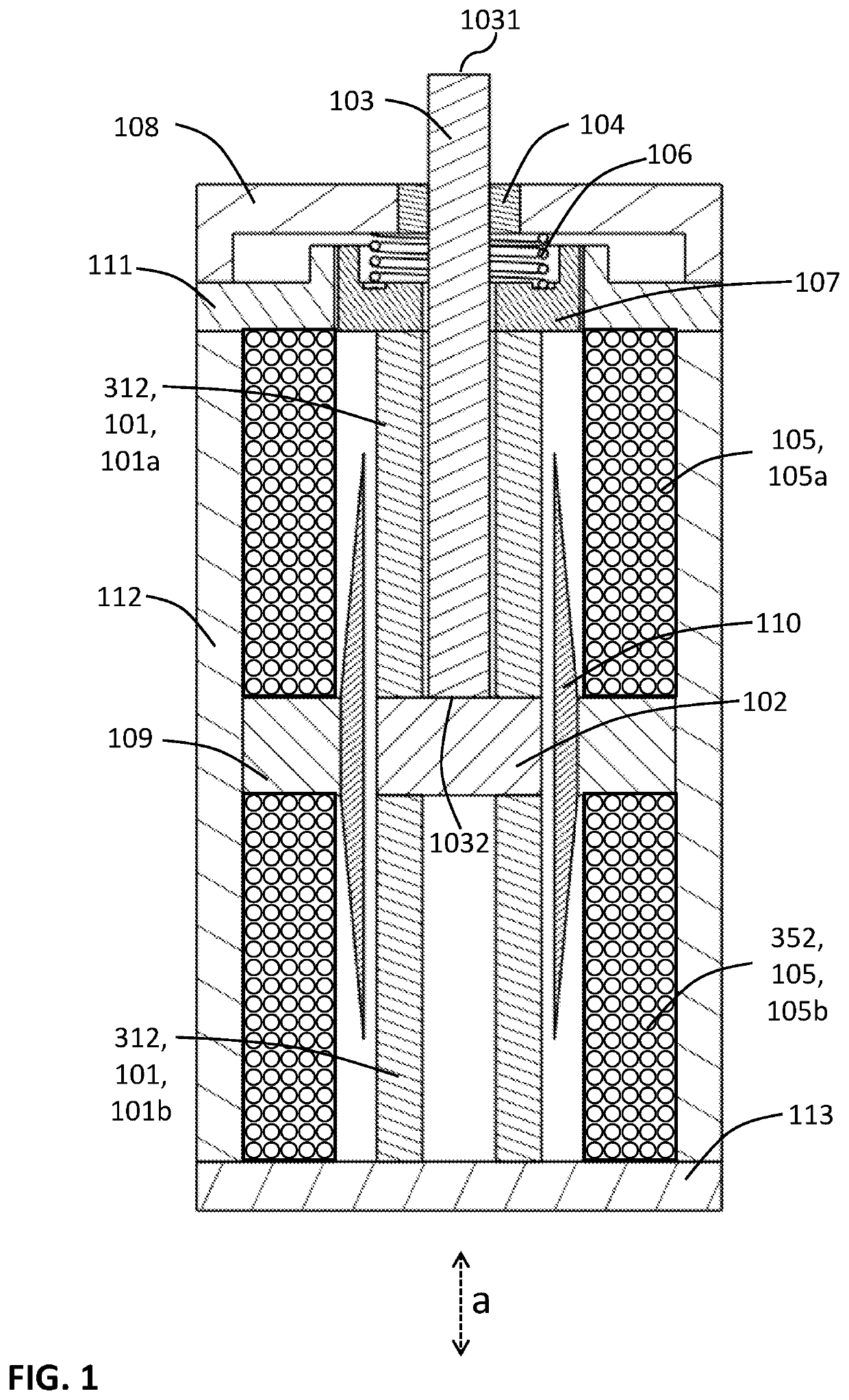
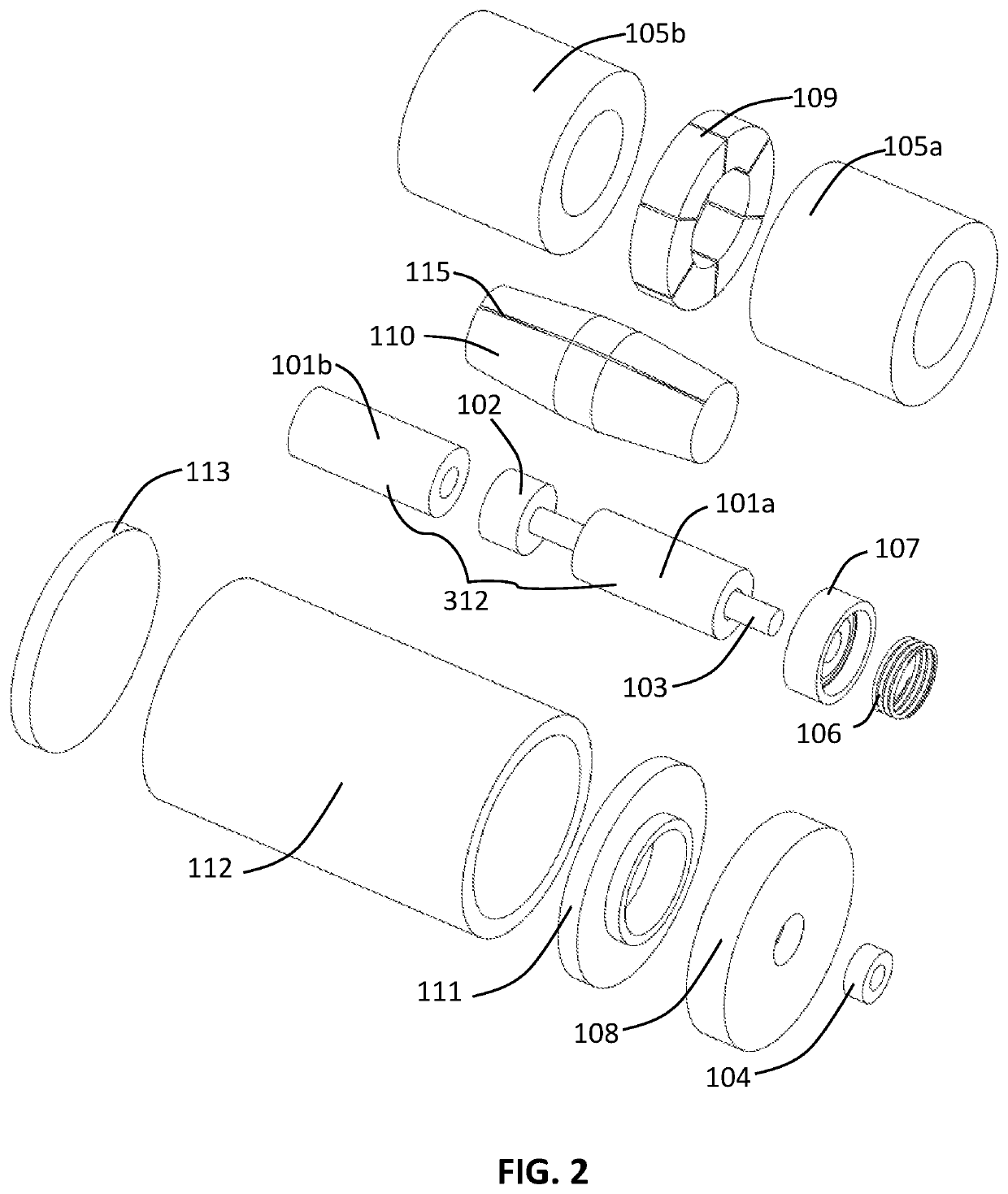
[0033]FIG. 1 and FIG. 2 are two views exemplifying the first mode of practice of a magnetostrictive actuator in accordance with the present invention. The inventive actuator depicted includes a magnetostrictive component 312, which includes two magnetostrictive elements 101, viz., 101a and 101b. Top magnetostrictive element 101a and bottom magnetostrictive element 101b are each in contact with center support 102 such that changes in the respective lengths of the magnetostrictive elements 101 correspondingly move center support 102 in the axial direction a. Center support 102 is moved vertically, either upward or downward, as shown by bidirectional arrow a in FIG. 1. Output shaft 103 is connected to center support 102 and therefore moves in one of two opposite axial-longitudinal directions in accordance with the axial-longitudinal movement of center support 102.

[0034]Output shaft 103 has an inner shaft end (lower shaft end 1032 as shown in FIG. 1) and an outer shaft end (upper shaft ...


PUM


Abstract

Exemplary practice of the present invention provides a magnetostrictive actuator characterized by linear force output and uniform magnetic biasing. A center bias magnet combined with a flux transfer tube produces a uniform magnetic bias down the length of a magnetostrictive component. Depending on the inventive embodiment, the magnetostrictive component may include one magnetostrictive element or a pair of collinear magnetostrictive elements. A center bias magnet, in combination with a flux transfer tube, drives magnetic flux through the magnetostrictive component (e.g., a series of magnetostrictive rods) in opposite directions, while surrounding drive coils apply flux in the same direction through the magnetostrictive component. The net response is substantially linear with respect to the drive coil current. The flux transfer tube applies distributed magnetic flux to the magnetostrictive component at a rate that ensures uniform magnetic flux density down the length of the magnetostrictive component.

Description

CROSS-REFERENCE TO RELATED APPLICATIONS[0001]This application is a divisional of U.S. nonprovisional patent application Ser. No. 15 / 717,658, filing date 27 Sep. 2017, hereby incorporated herein by reference, entitled “Magnetostrictive Actuator With Center Bias,” inventor John E. Miesner.STATEMENT OF GOVERNMENT INTEREST[0002]The invention described herein may be manufactured and used by or for the Government of the United States of America for governmental purposes without payment of any royalties thereon or therefor.BACKGROUND OF THE INVENTION[0003]The present invention relates to magnetostrictive actuators, more particularly to magnetostrictive actuators that seek to produce a linear force output and / or a uniform magnetic bias flux in the magnetostrictive elements.[0004]Magnetostrictive actuators offer great promise for applications that require a high force output over a wide bandwidth. However, magnetostrictive materials have two characteristics that limit their use. The first li...

Claims


Application Information

Patent Timeline
Patent Type & Authority Patents(United States)
IPC IPC(8): H01L41/12H01L41/06H02N2/04
CPCH01L41/12H01L41/06H02N2/043H02N2/04H10N35/80H10N35/00
Inventor MIESNER, JOHN E.
Owner THE UNITED STATES OF AMERICA AS REPRESENTED BY THE SECRETARY OF THE NAVY
Why Eureka
Try Eureka