Angle sensor

An angle sensor, sensor technology, applied in the direction of converting sensor output, instruments, measuring devices, etc., can solve the problems of uneven magnetic flux density of helical coils, magnetic flux leakage, resolver output error, etc., to improve detection accuracy and performance, The effect of homogenizing the magnetic flux density

Inactive Publication Date: 2015-07-15
AISAN IND CO LTD
View PDF16 Cites 0 Cited by
  • Summary
  • Abstract
  • Description
  • Claims
  • Application Information

AI Technical Summary

Problems solved by technology

[0008] However, in the flat resolver described in Patent Document 1, since the connecting wire for connecting the chip coils is substantially formed in a large loop, it may function as an antenna and be received from the outside. The influence of electromagnetic noise
[0009] In addition, in the resolver described in Patent Document 2, the shape of the helical coil wound in the forward direction is asymmetrical to the shape of the helical coil wound in the reverse direction, so that the magnetic flux density of each helical coil becomes non-uniform. , is easily affected by electromagnetic noise from the outside, which becomes the cause of the output error of the resolver
[0010] In addition, in the resolver described in Patent Document 3, since the secondary pattern of the transformer and the primary pattern of the transformer are provided separately from the two sheet coils, separate mounting work and wiring are required, resulting in poor reliability and productivity.
In addition, since the secondary pattern of the transformer and the primary pattern of the transformer are arranged to face each other only through a gap, there is a possibility that magnetic flux may leak between the two, which may cause a detection error and cause a problem in terms of reliability.

Method used


Image

  • Angle sensor
  • Angle sensor
  • Angle sensor

Examples


no. 1 Embodiment approach

[0051] Hereinafter, a first embodiment embodying the angle sensor of the present invention will be described in detail with reference to the drawings.

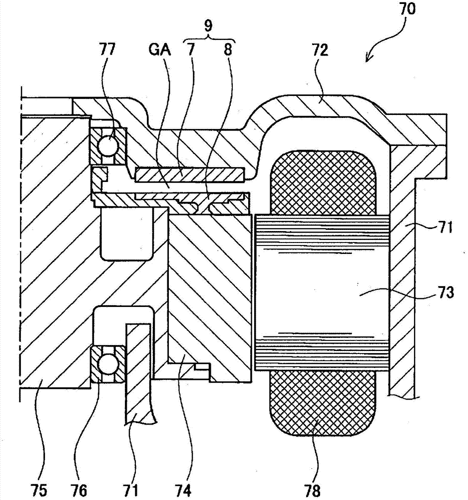
[0052] figure 1 It is a sectional view showing a part of the motor 70 to which the angle sensor 9 of this embodiment is mounted. The motor 70 includes: a motor case 71; a case cover 72 for covering the opening of the motor case 71; a motor stator 73 fixed to the motor case 71; a motor rotor 74 provided inside the motor stator 73; A motor shaft 75 integrally provided at the center of the motor rotor 74; a pair of bearings 76, 77 for rotatably supporting the motor shaft 75 between the motor housing 71 and the housing cover 72.

[0053] The motor housing 71 and the housing cover 72 are formed by casting aluminum alloy or the like. The motor stator 73 has a coil 78 and is fixed to the inner periphery of the motor housing 71 . The motor stator 73 is excited by energizing the coil 78 to generate magnetic force.

[0054] The moto...

no. 2 Embodiment approach

[0110] Next, a second embodiment of an angle sensor of the present invention will be described in detail with reference to the drawings.

[0111] Figure 23 is a front cross-sectional view showing the angle sensor 301 and the motor 302 provided with the angle sensor 301 according to this embodiment (hereinafter, for convenience, figure 1 orientation as the front view). The motor 302 includes: a motor housing 311 having a substantially disc-shaped appearance; a rotating shaft 314 covered by the motor housing 311 and rotatably supported at the inner center of the motor housing 311 via bearings 312, 313; a motor rotor 315, It is fixed on the outer circumference of the rotating shaft 314 inside the motor housing 311 ; the motor stator 316 is fixed on the inner side of the motor housing 311 through a gap on the outer circumference side of the motor rotor 315 . A coil 317 is provided on the motor stator 316 .

[0112] exist Figure 23 Among them, a housing portion 311 a for hous...

no. 3 Embodiment approach

[0129] Next, a third embodiment of the angle sensor of the present invention will be described in detail with reference to the drawings.

[0130] Figure 29 is part of the representation of the angle sensor based on Figure 27 enlarged sectional view of the . This embodiment differs from the second embodiment in the arrangement of the annular facing portions 323c and 335a. That is, in the rotor-side ring-shaped metal member 323 , the ring-shaped opposing portion 323 c is disposed on the outer peripheral portion of the metal member 323 . Further, a groove 323d in which the resolver coil 341 is arranged is formed on the side of the annular facing portion 323c close to one side surface in the axial direction (the surface 321a of the rotor substrate 321). On the other hand, in the stator-side ring-shaped metal member 335 , the ring-shaped facing portion 335 a is disposed at a position facing the ring-shaped facing portion 323 c of the rotor-side ring-shaped metal member 323 . ...


PUM


Abstract

An angle sensor includes a sensor rotor formed with a planar coil and a sensor stator including a multi-X type planar coil placed to face a surface of the sensor rotor. On a stator substrate of the sensor stator are provided forward-direction planar coils and reverse-direction planar coils, and positive and negative terminals adjacently arranged. The forward-direction and reverse-direction planar coils are connected in series through connecting wires. One of both ends of the series-connected planar coils is connected to the positive terminal through the wire and the other end is connected to the negative terminal through the wire. The wires are arranged along arrangement of the series-connected planar coils but in a range less than a full circle of the arrangement. A turn-back connecting wire extending from one end of the series of planar coils is arranged along the other connecting wire and connected to the negative terminal.

Description

technical field [0001] The present invention relates to an angle sensor for detecting the rotation angle of an output shaft of an electric motor or an engine. Background technique [0002] Conventionally, as such a technique, for example, a flat resolver (resolver) described in Patent Document 1 below is known. This flat resolver includes a fixed side core, a movable side core, and a plurality of multi-X-shaped sheet coils (sheet coils) provided on the surface of the fixed side core. Furthermore, the connecting wires connecting the plurality of sheet coils are connected so as to go around the fixed-side core substantially once. [0003] In addition, there is known a chip-coil resolver described in Patent Document 2 below. The resolver has an excitation phase coil and a detection phase coil. In the excitation phase coil, a helical coil (planar coil) is provided on the front side of the insulating film layer, and a helical coil (planar coil) wound in the opposite direction ...

Claims


Application Information

Patent Timeline
Patent Type & Authority Patents(China)
IPC IPC(8): G01B7/30
CPCG01D5/00G01B7/30G01D5/2291
Inventor 木野久志金光亮次郎中村和弘铃木真矢
Owner AISAN IND CO LTD
Why Eureka
Try Eureka