
System and method for operating utility vehicles

a utility vehicle and system technology, applied in vehicle position/course/altitude control, process and machine control, instruments, etc., can solve the problems of increased accidents, increased risk of accidents, and increased requirements for drivers, so as to achieve a high degree of safety and reduce the risk of accidents

Active Publication Date: 2022-04-12
KNORR BREMSE SYST FUER NUTZFAHRZEUGE GMBH
View PDF17 Cites 2 Cited by
  • Summary
  • Abstract
  • Description
  • Claims
  • Application Information

AI Technical Summary

Benefits of technology

The system significantly reduces accident risks and optimizes driver working hours by enabling fully autonomous operations in restricted areas, ensuring efficient vehicle utilization and enhanced safety by decoupling the driver from interaction with the vehicle during critical tasks.

Problems solved by technology

Problems may however occur when the utility vehicle is used in specific areas where the surroundings are unique, space is limited and specific maneuvers need to be executed that often place high requirements on the driver.
Such specific areas are for example loading stations or goods yards that often do not provide enough space and yet require the driver to maneuver in various directions.
A lot of time is then lost in particular when the driver has to execute specific, non-standardized maneuvers within areas with which he is not familiar and that pose particular difficulties.
Especially because the driver often feels uncertain in such situations, the likelihood of accidents is increased.
By way of example, accidents frequently occur when the driver has to reverse a utility vehicle into a tight area in a complex environment.
Even though external interfering influences are fairly low in such environments / areas and the speed of the utility vehicle is fairly slow, such systems only offer insufficient solutions in this respect.
However, these systems are incomplete as the driver either always retains responsibility for the vehicle or else the system only takes over relatively simple control operations for the vehicle (that is to say acts as an active navigation system).
The cited documents do not disclose any solutions for these cases of application.

Method used


Image

  • System and method for operating utility vehicles
  • System and method for operating utility vehicles
  • System and method for operating utility vehicles

Examples


Embodiment Construction

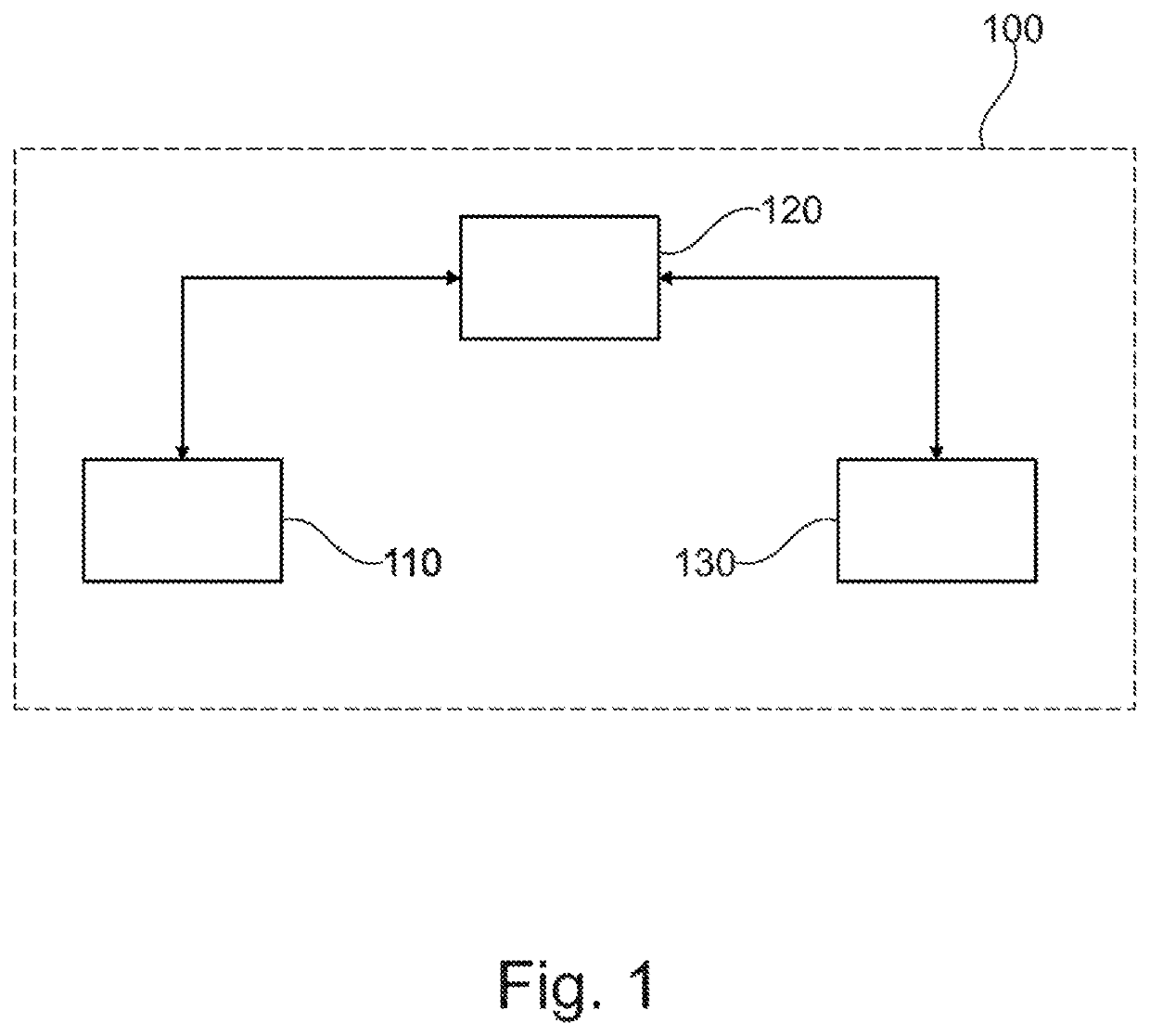
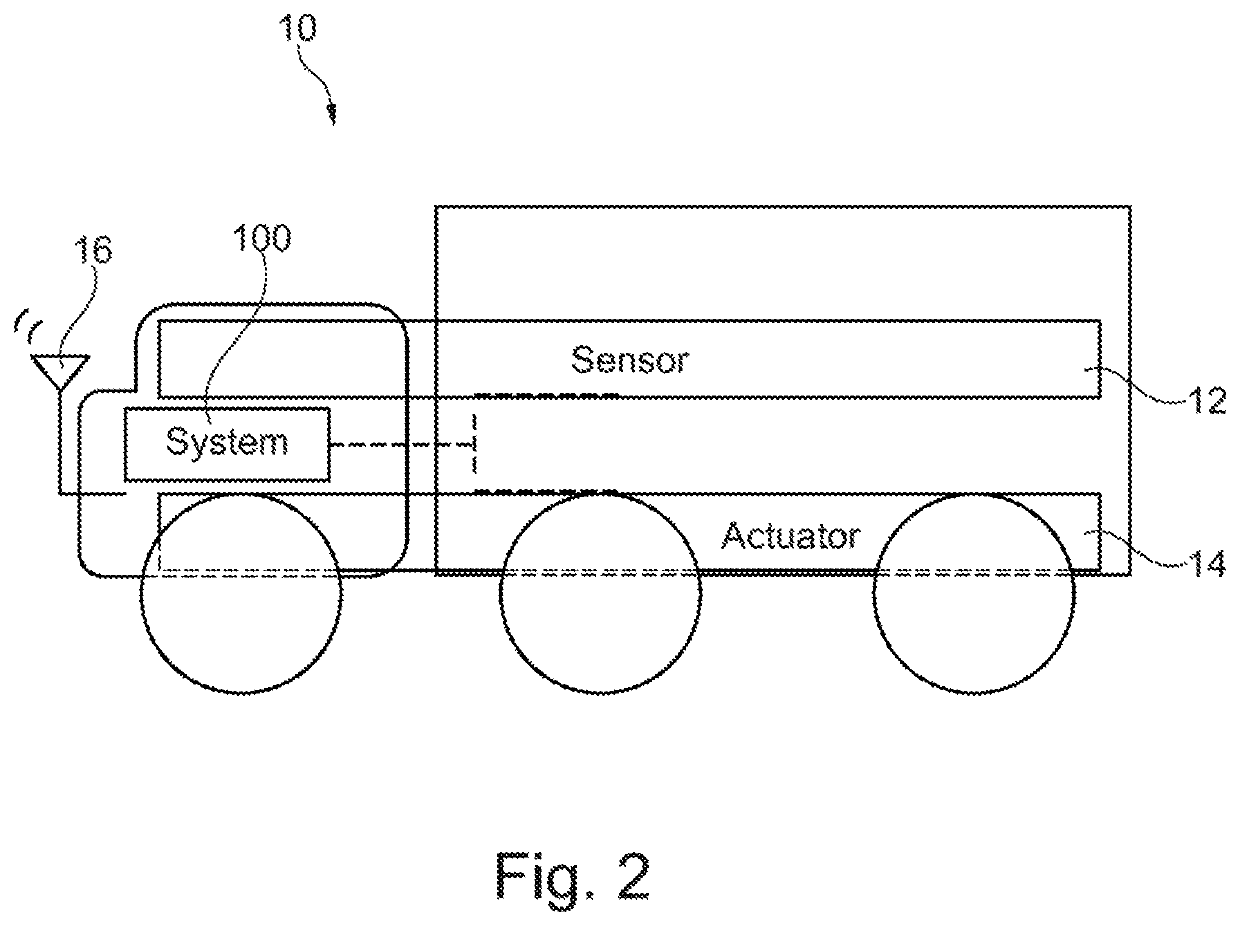
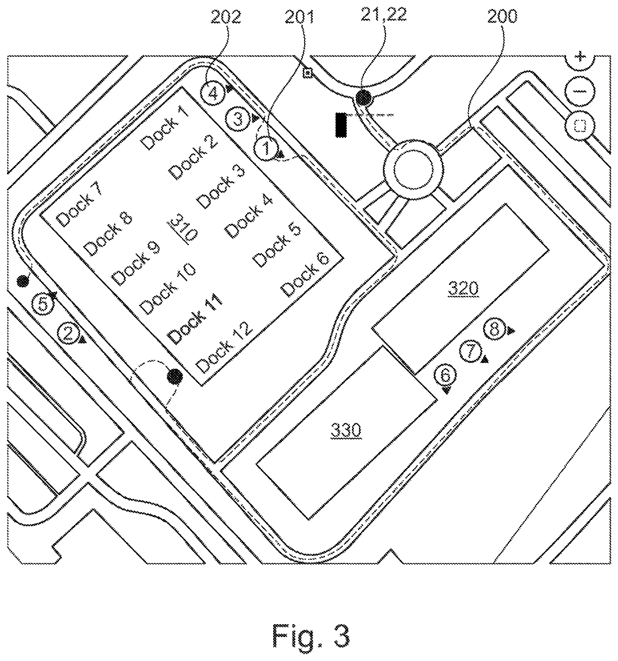
[0038]FIG. 1 shows an exemplary embodiment for a system 100 that is suitable for operating a utility vehicle in a restricted area, without a driver having to be present in the utility vehicle. The restricted area comprises an entrance, an exit and has a predetermined target point. The system 100 comprises a transfer module 110, a movement module 120 and a performance module 130. The transfer module 110 is configured to transfer control of the utility vehicle, and to do so at the entrance: from the driver of the utility vehicle to the system, and at the exit: from the system to the driver of the utility vehicle. The movement module 120 is configured to move the utility vehicle from the entrance to the predetermined target point 201 and from the predetermined target point to the exit autonomously. The performance module 130 is configured to perform an action on the utility vehicle autonomously while the utility vehicle is situated at the predetermined target point. This action changes...


PUM


Abstract

A system for operating a driverless utility vehicle in a restricted area, including: a transfer module for transferring control of the utility vehicle at an entrance: from the driver of the utility vehicle to the system, and at an exit: from the system to the driver of the utility vehicle, wherein the restricted area has the entrance, the exit and a predetermined target point; a movement module for autonomously moving the utility vehicle from the entrance to the predetermined target point and from the predetermined target point to the exit; and a performance module for autonomously performing an action on the utility vehicle while the utility vehicle is situated at the predetermined target point, so as to change a state of the utility vehicle by the action. Also described are a related management system, a method, and a computer readable medium.

Description

FIELD OF THE INVENTION[0001]The present invention relates to a system and to a method for operating driverless utility vehicles, and in particular to autonomous operation of utility vehicles in a restricted area.BACKGROUND INFORMATION[0002]In the use of utility vehicles, transport time and the utilization of the driver's working hours are significant factors for the effectiveness of a vehicle fleet. The majority of transport typically takes place on public roads with standardized rules, which often do not place any high requirements on the driver. Problems may however occur when the utility vehicle is used in specific areas where the surroundings are unique, space is limited and specific maneuvers need to be executed that often place high requirements on the driver. Such specific areas are for example loading stations or goods yards that often do not provide enough space and yet require the driver to maneuver in various directions.[0003]A lot of time is then lost in particular when ...

Claims


Application Information

Patent Timeline
Patent Type & Authority Patents(United States)
IPC IPC(8): G05D1/02G08G1/14G08G1/16
CPCG05D1/0225G05D1/0214G05D1/0282G08G1/148G08G1/164G05D2201/0213G05D2201/0216
Inventor BALOGH, LEVENTEHORVATH, CSABANEMETH, HUBATIHANYI, VIKTORFRANK, PETER
Owner KNORR BREMSE SYST FUER NUTZFAHRZEUGE GMBH
Learn More