
Ball screw assembly

Active Publication Date: 2022-04-05
LEE SZU YING
View PDF24 Cites 0 Cited by
  • Summary
  • Abstract
  • Description
  • Claims
  • Application Information

AI Technical Summary

Benefits of technology

The patent text describes a novel design for a ball screw assembly used in manufacturing precision equipment. The design includes an open nut with an axial opening, which allows it to move along a guider without interfering with a supporting holder. The open nut design also includes resilient mechanisms on the supporting holder to prevent detachment, which ensures the manufacturing precision of the assembly is not affected. Additionally, the design provides a dustproof function using open shields. The design also allows for flexibility in the application of different numbers of circulators and open shields based on the requirements of the carrier.

Problems solved by technology

Furthermore, when the supporting holder is at a position away from the screw, the portion of the screw corresponding to the supporting holder may sag due to its weight.
As a result, when the open nut passes the portion of the screw having the supporting holder at the position away from the screw, the screw may encounter deflection, or the balls may not roll in the threaded groove properly due to the bending of the screw.
Consequently, during the application of the ball guider device, the manufacturing precision becomes an issue and is to be considered.

Method used


Image

  • Ball screw assembly
  • Ball screw assembly
  • Ball screw assembly

Examples


Embodiment Construction

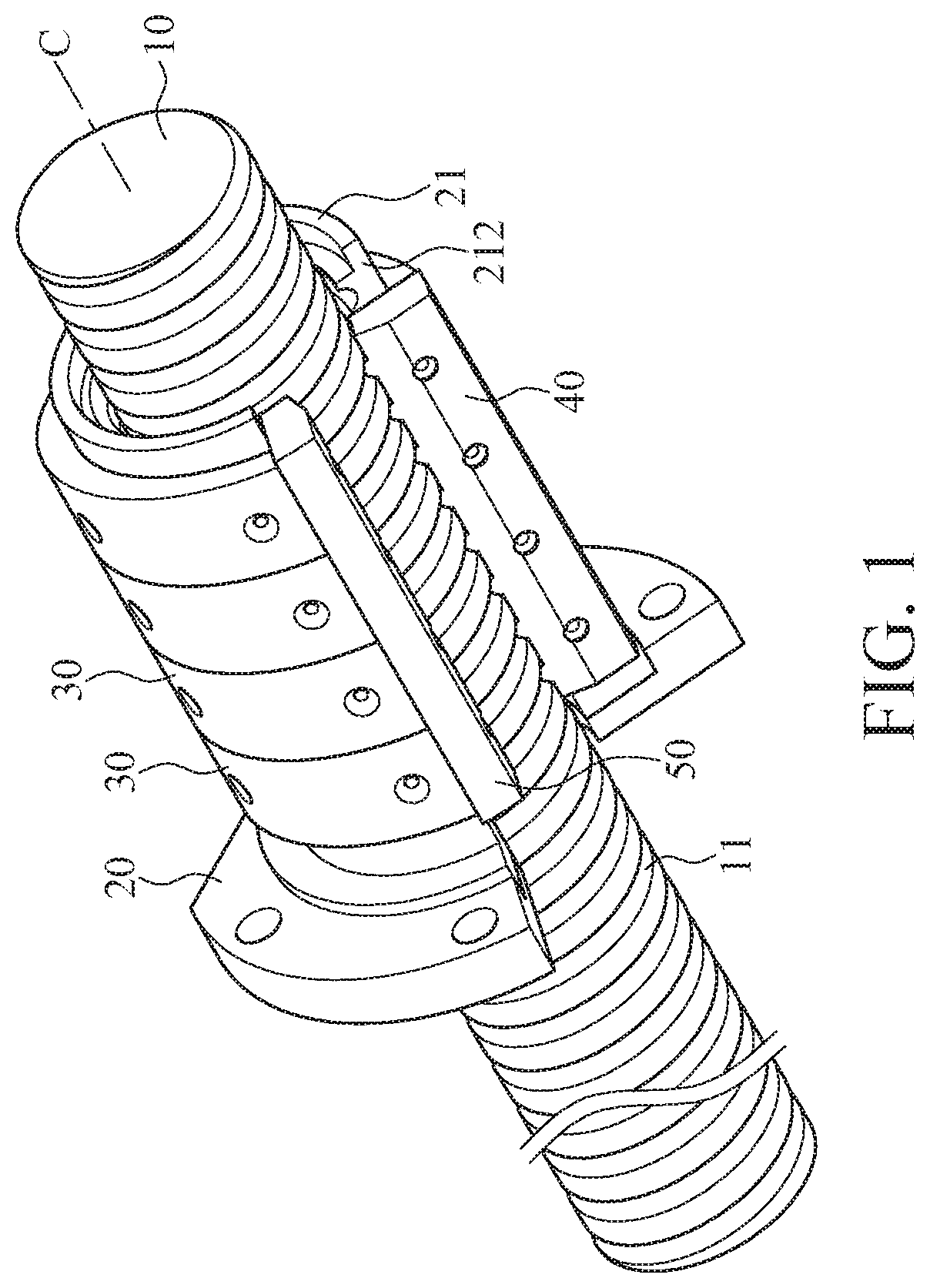
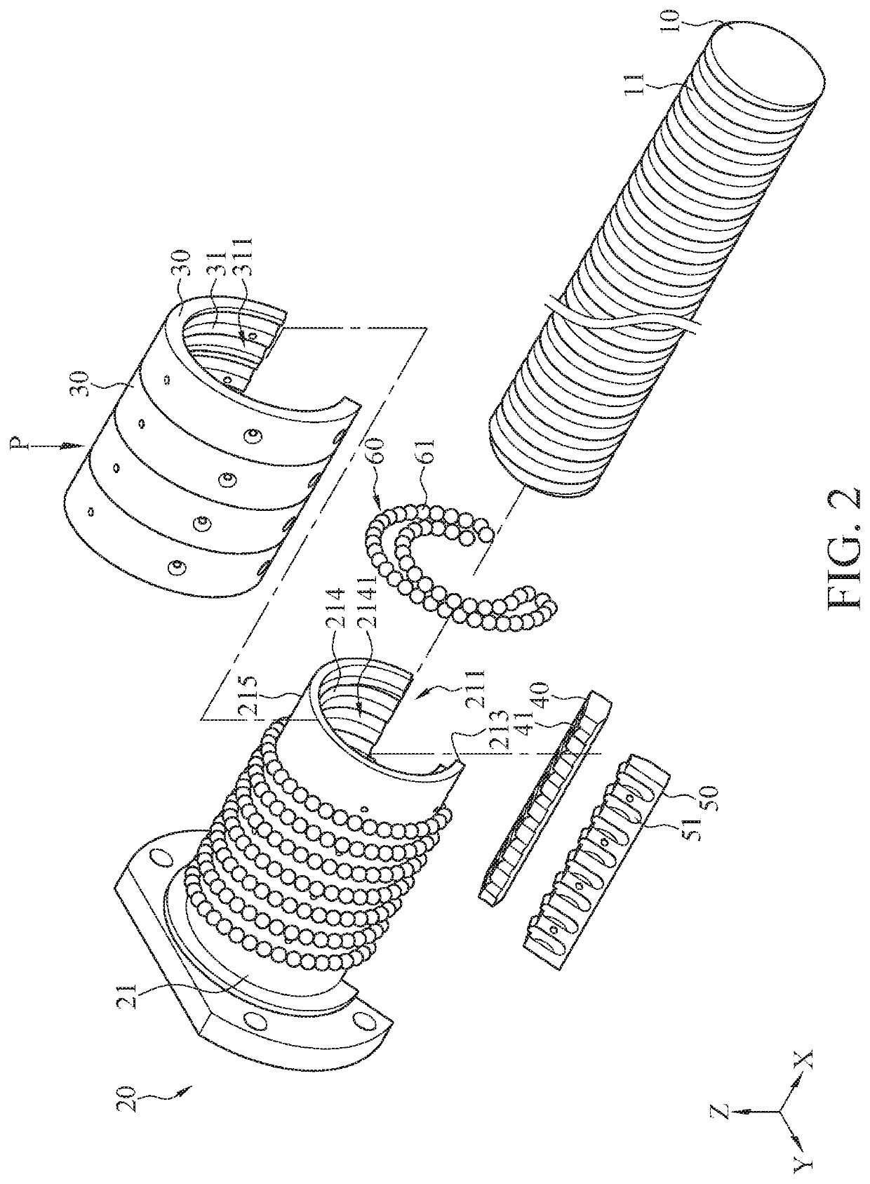
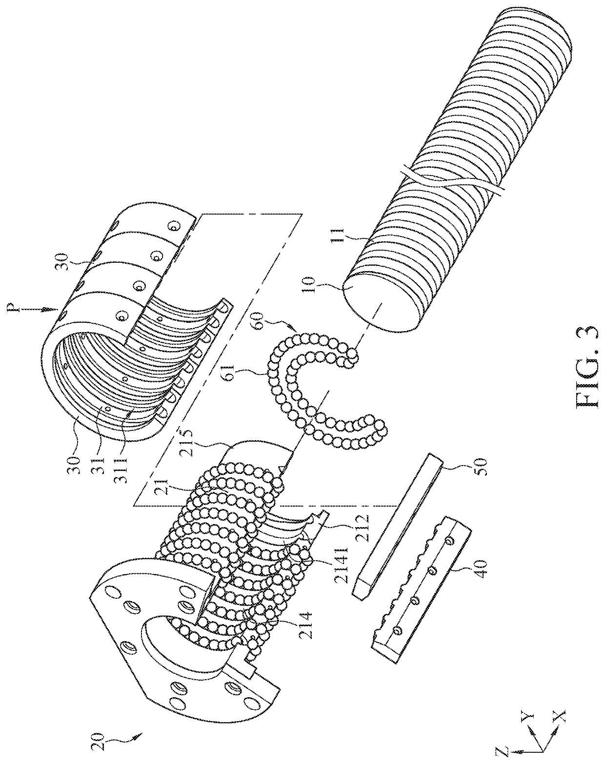
[0032]Please refer to FIGS. 1 to 5. FIG. 1 illustrates a perspective view of a ball screw assembly according to a first embodiment of the instant disclosure. FIG. 2 illustrates an exploded view of the ball screw assembly of the first embodiment. FIG. 3 illustrates an exploded view of the ball screw assembly of the first embodiment from another perspective. FIG. 4 illustrates a bottom view of open shields of the ball screw assembly of the first embodiment. FIG. 5 illustrates a top view of a second circulator of the ball screw assembly of the first embodiment.

[0033]As shown in FIGS. 1 and 2, in this embodiment, the ball screw assembly comprises a guider 10, an open nut 20, a plurality of open shields 30, a first circulator 40, a second circulator 50, and a plurality of ball circulating assemblies 60. The guider 10 may be, for example, a screw or a conversion rod. In this embodiment, the guider 10 is a screw for an illustrative example. As shown in FIG. 1, the guider 10 has a central a...


PUM


Abstract

A ball screw assembly includes a guider, an open nut, open shields, a first circulator, a second circulator, and ball circulating assemblies. The open nut is slidably fitted over the guider and includes an axial cylinder having an axial opening. Inner spiral channels of the axial cylinder and spiral channels of the guider form inner ball races. The open shields are coaxially fitted over the axial cylinder. An inner peripheral wall of each of the open shields and an outer annular wall of the axial cylinder form an outer ball race. The first circulator and the second circulator are disposed on the axial cylinder corresponding to the open shields. The inner ball races, first curves of the first circulator, the outer ball races, and second curves of the second circulator form ball circulating races, and the ball circulating assemblies roll in the ball circulating races.

Description

CROSS-REFERENCE TO RELATED APPLICATION[0001]This non-provisional application claims priority under 35 U.S.C. § 119(a) to Patent Application No. 201911205361.9 filed in China, P.R.C. on Nov. 29, 2019, the entire contents of which are hereby incorporated by reference.BACKGROUNDTechnical Field[0002]The instant disclosure relates to a ball screw assembly, in particular, to a ball screw assembly with an open nut having an axial opening.Related Art[0003]The ball screw device known to the inventor is provided for converting a rotation motion into a linear motion through the cooperation between the screw and the nut. By the cooperation between the ball nut provided with balls rolling in the circulating race and the screw provided with a spiral groove, the friction between the ball nut and the screw can be reduced during the operation.[0004]Most of the ball nuts known to the inventor have complete cylinder shapes. When the length of the screw is longer and is provided with a supporting holde...

Claims


Application Information

Patent Timeline
IPC IPC(8): F16H25/20F16H25/22
CPCF16H25/2214F16H25/2233F16H25/2228F16H25/24F16H2025/2436F16H25/2223
Inventor LEE, SZU-YING
Owner LEE SZU YING
Learn More