
Sight system incorporating optical components such as lasers and/or cameras

Active Publication Date: 2022-03-01
MORSE BRADLEY OWEN
View PDF16 Cites 1 Cited by
  • Summary
  • Abstract
  • Description
  • Claims
  • Application Information

AI Technical Summary

Benefits of technology

The present invention is a device that uses lasers to bracket a target between two beams and determine the projectile's axis and impact point. It works with both stationary and moving targets and can be used with wedges, such as bows. The lasers do not cover up the point of impact. The lasers have a slight divergence, which makes it easier to observe the target from a distance. The device can also rotate about the projection axis to effectively bracket the target. It is useful in various environments and can help users and supervisors evaluate shots before taking them.

Problems solved by technology

Yet, optic sights are not without drawbacks.
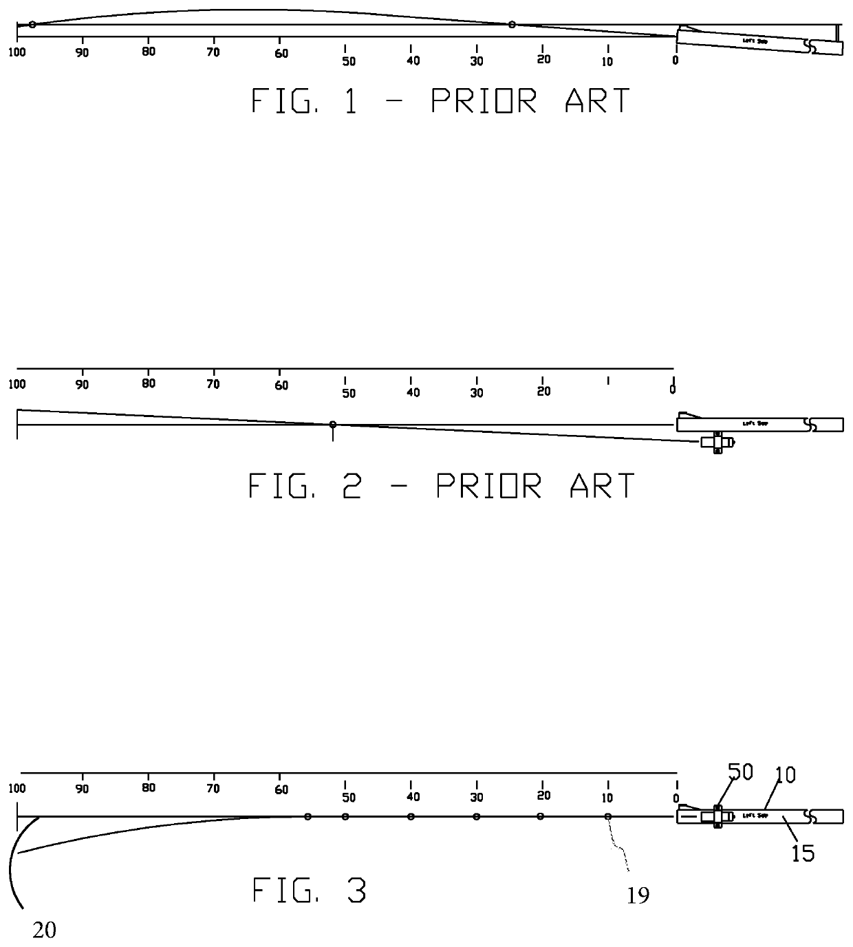
Single optic systems have drawbacks that depend on where the optics are mounted relative to the projectile axis.
This is disadvantageous as the target may not be located at either of the specific distances most often resulting in inaccurate placement of the optical focal point (e.g. a laser reflection point) on the target with respect to the true projectile axis.
A further drawback of top mounted optics is that their placement may interfere with the use of the traditional barrel sight.
There are also drawbacks when the optic is mounted to the bottom of the barrel.
Further, there are drawbacks with a side mounted optic, which is typically parallel to the projectile axis or convergent with the projectile axis.
When, for example a laser optic is used, and the laser beam is convergent with the projectile axis, the drawback is that the laser beam is only accurate at the point of convergence.
When the laser beam is parallel to the projectile axis, the drawback is that the laser is never fully accurate as it never accurately indicates the location of the projectile path.
Further, there is no way to know how much to compensate for the offset.
When the laser beam is convergent with the projectile axis, the drawback is that the laser beam is only accurate at the point of convergence.

Method used


Image

  • Sight system incorporating optical components such as lasers and/or cameras
  • Sight system incorporating optical components such as lasers and/or cameras
  • Sight system incorporating optical components such as lasers and/or cameras

Examples


Embodiment Construction

[0073]While the invention will be described in connection with one or more preferred embodiments, it will be understood that it is not intended to limit the invention to those embodiments. On the contrary, it is intended to cover all alternatives, modifications and equivalents as may be included within the spirit and scope of the invention as defined by the appended claims.

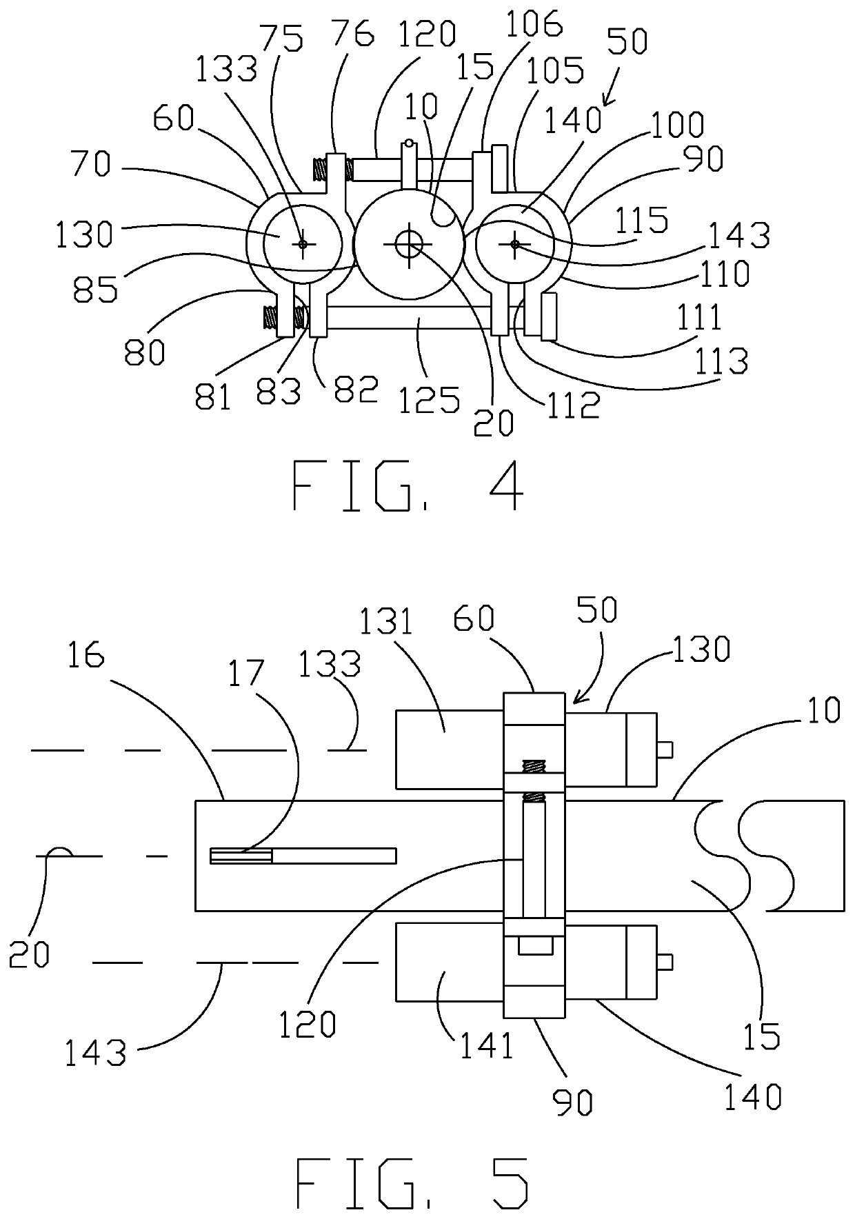
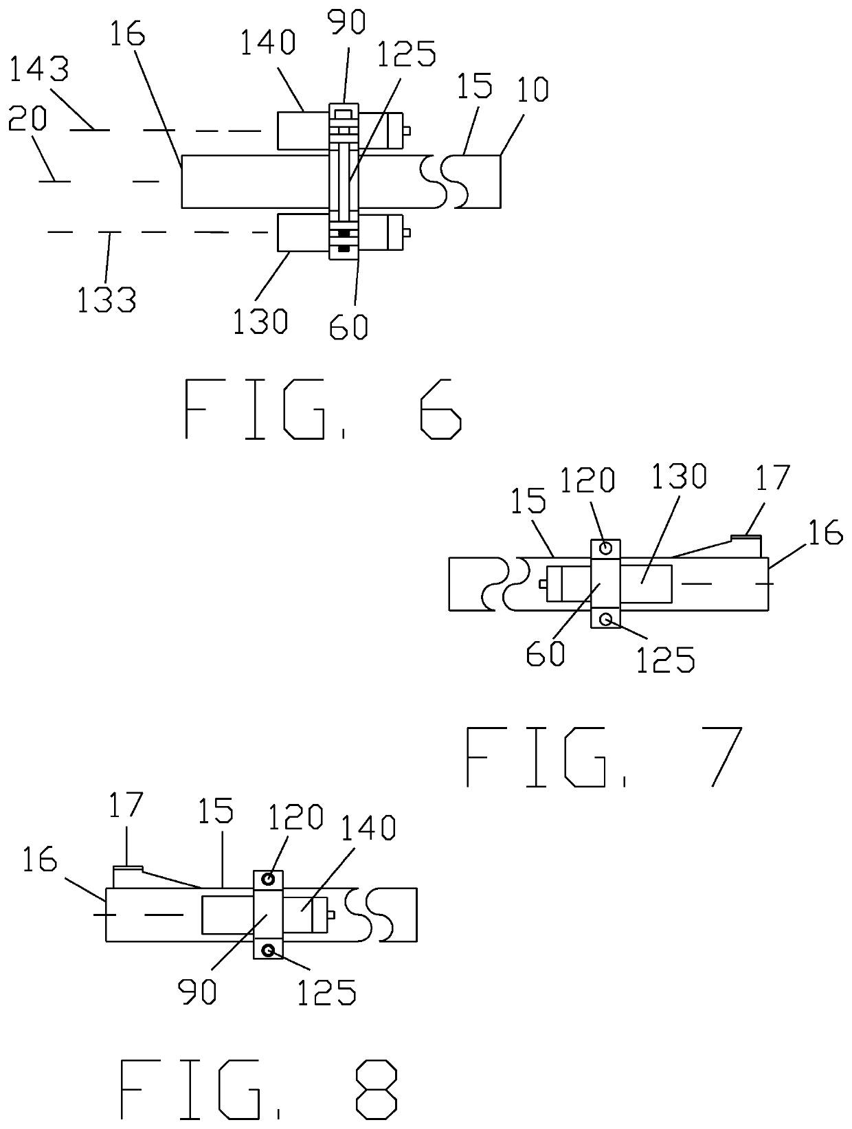
[0074]A user 5 can use a firearm 10 with the present invention, as seen in FIGS. 3-13. The firearm 10 has a barrel 15 with an end 16 having a barrel sight 17. A projectile axis 20 is colinear with a longitudinal axis of the barrel 15 (barrel axis). The user 5 can project a projectile 19 along the projectile or projection axis 20 at a target 30. It is appreciated that while a traditional bullseye is illustrated, that the target can be any suitable target. Also, the firearm 10 is illustrated for exemplary purposes only, and the present invention is useful with any item that can project a projectile along a projectil...


PUM


Abstract

The present invention relates to a sight system incorporating offset optical components. One embodiment is a sight system supporting multiple laser beams that are used simultaneously. As such, an assembly having two clamps is provided. Each clamp can hold a laser on opposite sides of a firearm barrel. The lasers can be diametrically opposed on the barrel wherein the lasers are in plane with a projectile axis. The lasers can project at the same time to bracket the location on the target of where the projectile hit impact. In another embodiment, the assembly, again with two clamps, is adapted for use with a bow, wherein the clamps support lasers that are in plane with the projectile axis. In another embodiment, the optical component is one or more cameras, wherein reticles can be displayed on a screen to bracket a target.

Description

[0001]This United States utility patent application claims priority on and the benefit of provisional application 62 / 653,454 filed Apr. 5, 2018, and also claims priority on and the benefit of provisional application 62 / 785,799 filed Dec. 28, 2018, the entire contents of both being hereby incorporated herein by reference.BACKGROUND OF THE INVENTION1. Field of the Invention[0002]The present invention relates to a sight system incorporating optical components, which can be a sight system utilizing multiple laser beams simultaneously or a sight system using one or more cameras.2. Description of the Related Art[0003]Optics, such as scopes and lasers, have greatly improved accuracy of firearms, bows and other items that project a projectile. Yet, optic sights are not without drawbacks.[0004]Single optic systems have drawbacks that depend on where the optics are mounted relative to the projectile axis. Optics that are mounted to the top of a barrel, for example, are truly only accurate at ...

Claims


Application Information

Patent Timeline
IPC IPC(8): F41G3/06F41G11/00F41J5/10F41G1/54
CPCF41G11/003F41G1/545F41G3/065F41J5/10F41G3/165F41G1/35F41G1/467
Inventor MORSE, BRADLEY OWEN
Owner MORSE BRADLEY OWEN
Learn More