
Input device, automated teller machine and method

a technology of input device and automatic teller machine, which is applied in the direction of automatic teller machine, data processing application, instruments, etc., can solve the problems of increasing costs and sophistication, increasing the risk of the device becoming a target for unauthorized access, and increasing the value of the content, so as to increase the cost and sophistication, and reduce the cost

Active Publication Date: 2022-02-22
DIEBOLD NIXDORF SYST GMBH
View PDF13 Cites 0 Cited by
  • Summary
  • Abstract
  • Description
  • Claims
  • Application Information

AI Technical Summary

Benefits of technology

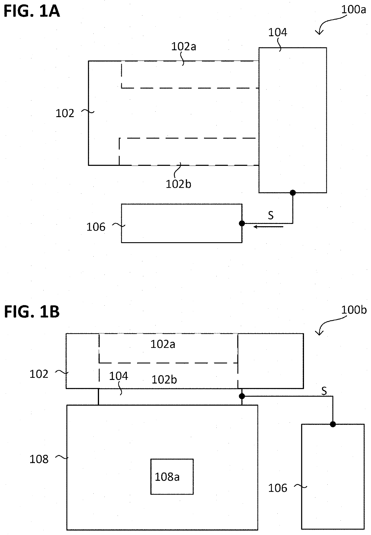
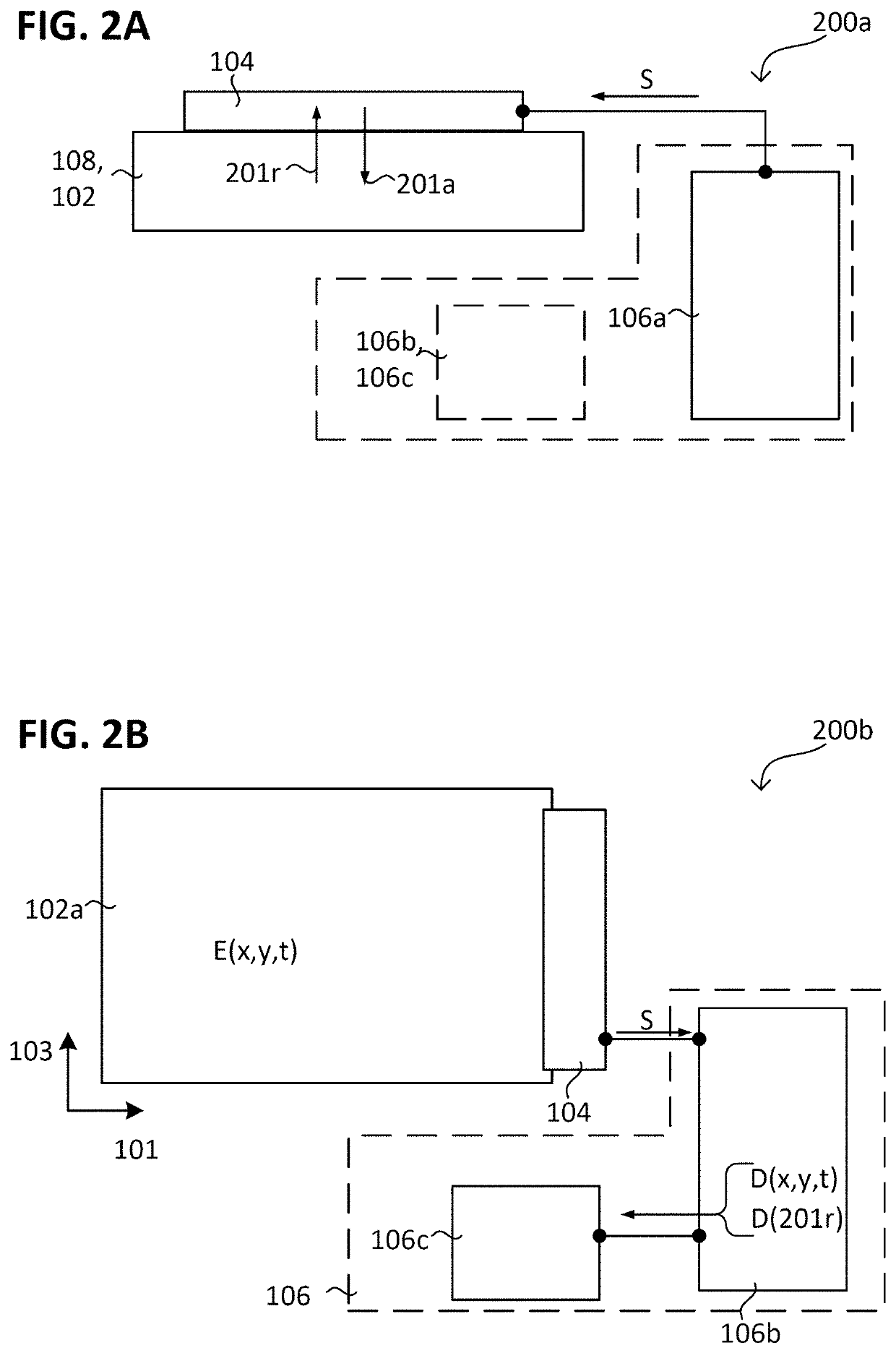
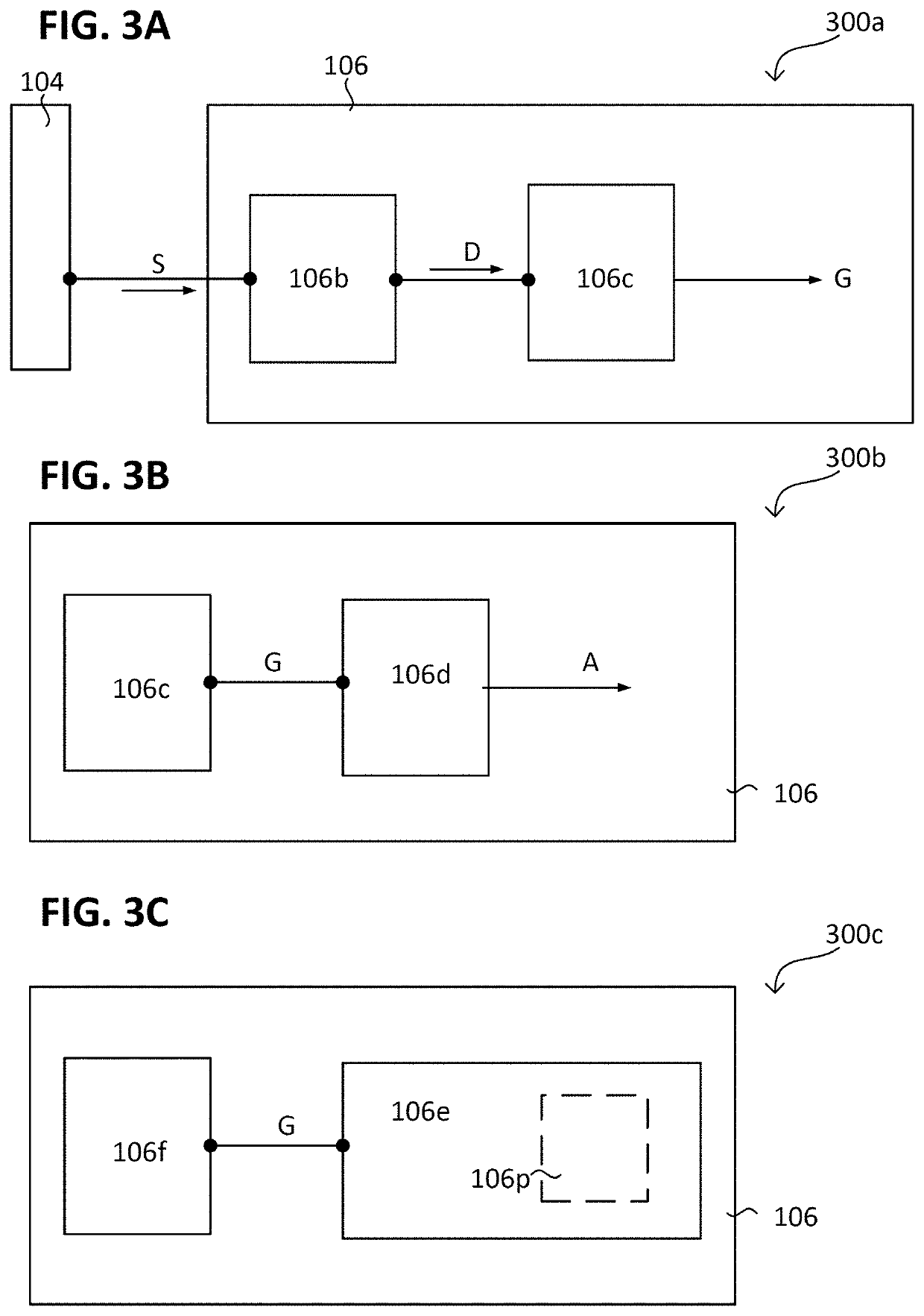
The invention is about a new input device, automated teller machine, and method that allows for user input to be captured and monitored simultaneously. This is done by using sensors on the input device to capture the user's input and the state of the machine or object being monitored. This low-cost and sophisticated solution helps prevent unauthorized access and manipulation of the machine. The invention can also be used to capture the state of the user's input and monitor the object or support being monitored. The control apparatus can use the electromechanical transducer structure to perform both user control functions and integrity monitoring. The control apparatus can also detect and prevent damage or manipulation to the object being monitored. The invention provides an effective and affordable way to protect against unauthorized access and manipulation of self-service terminals.

Problems solved by technology

The risk of the device becoming a target for unauthorized access increases with the value of its content.
However, such a self-service terminal can be protected against external access only with difficulty owing to the circumstance that it is meant to be accessible (i.e. is exposed) to the user.
This increases the costs and sophistication.
This is unable to prevent unauthorized access per se, however.
This again increases the costs and sophistication, however.

Method used


Image

  • Input device, automated teller machine and method
  • Input device, automated teller machine and method
  • Input device, automated teller machine and method

Examples


Embodiment Construction

[0060]In the detailed description that follows, reference is made to the accompanying drawings, which form part of said description and show for illustration purposes specific embodiments in which the invention can be implemented. In this regard, direction terminology such as, for example, “at the top”, “at the bottom”, “at the front”, “at the back”, “front”, “rear”, etc. is used with respect to the orientation of the figure(s) described. Since components of embodiments can be positioned in a number of different orientations, the direction terminology serves for illustration and is not restrictive in any way whatsoever. It goes without saying that other embodiments can be used and structural or logical changes can be made, without departing from the scope of protection of the present invention. It goes without saying that the features of the various illustrative embodiments described herein can be combined with one another, unless specifically indicated otherwise. Therefore, the det...


PUM


Abstract

An input device has a support that has a user control area and that has a coupling area for coupling an object to be monitored to the input device; an electromechanical transducer structure that is coupled both to the user control area and to the coupling area; and a control apparatus that uses the electromechanical transducer structure to implement a user control function of the user control area and further to implement mechanical integrity monitoring of the object to be monitored and / or the support.

Description

CROSS-REFERENCE TO RELATED APPLICATIONS[0001]This application is the US national stage entry of application PCT / EP2018 / 052928, filed Feb. 6, 2018, and which claims priority to and the benefit of EP17155853.9.BACKGROUND AND SUMMARY[0002]The invention relates to an input device, an automated teller machine and a method.[0003]In general, self-service terminals can be used in order to provide a user with various goods in an automated manner, e.g. when the user requests said goods at the self-service terminal. By way of example, a self-service terminal can have an automated teller machine at which the user can pay in or withdraw banknotes independently and can perform other banking transactions.[0004]The goods (e.g. banknotes) can be held in a reservoir of the self-service terminal. Owing to its content, the reservoir may be of particular interest for criminal activities aiming to acquire its content. The risk of the device becoming a target for unauthorized access increases with the val...

Claims


Application Information

Patent Timeline
Patent Type & Authority Patents(United States)
IPC IPC(8): G06Q40/00G07F19/00G06Q20/10
CPCG07F19/20G06Q20/1085G07F7/1033
Inventor DIETZ, OLIVER
Owner DIEBOLD NIXDORF SYST GMBH
Learn More