
Ratchet wrench

a ratchet wrench and wrench technology, applied in the field of hand tools, can solve the problems of affecting work efficiency and the inability of the wrench to rotate smoothly, and achieve the effect of smooth rotation, increased durability and operating efficiency of the ratchet wrench

Active Publication Date: 2022-02-22
STANLEY CHIRO INT
View PDF14 Cites 0 Cited by
  • Summary
  • Abstract
  • Description
  • Claims
  • Application Information

AI Technical Summary

Benefits of technology

The ratchet wrench in this invention has a main advantage in that it prevents the switching member from coming off the main body and allows for smooth rotation, which makes it more durable and efficient in use.

Problems solved by technology

However, the switch of the conventional ratchet wrench can sway when being switched so that the switch cannot be rotated smoothly.
The switch may depart from the main body and result in breaking up into components, which influences efficiency of work.

Method used


Image

  • Ratchet wrench
  • Ratchet wrench
  • Ratchet wrench

Examples


Embodiment Construction

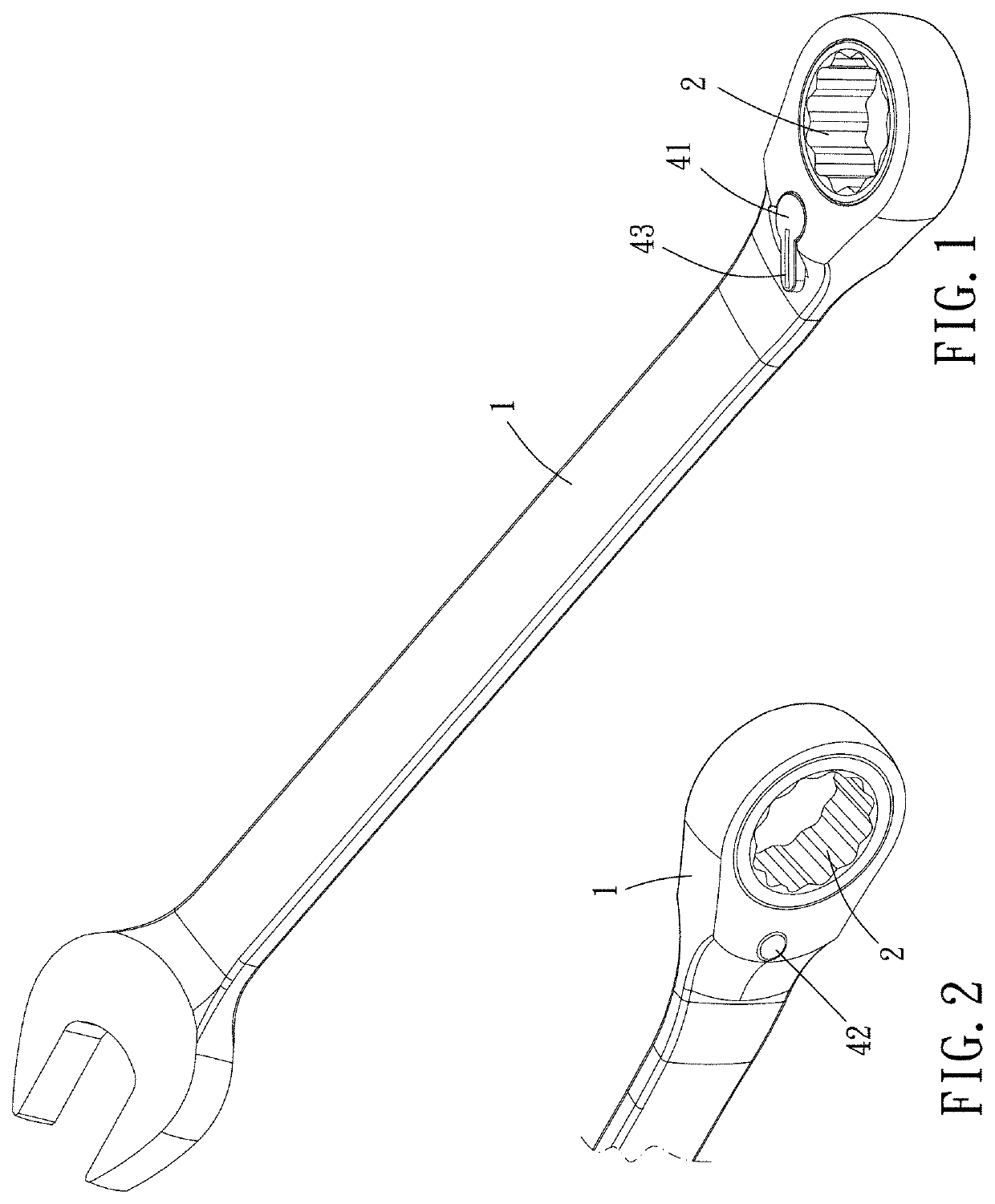
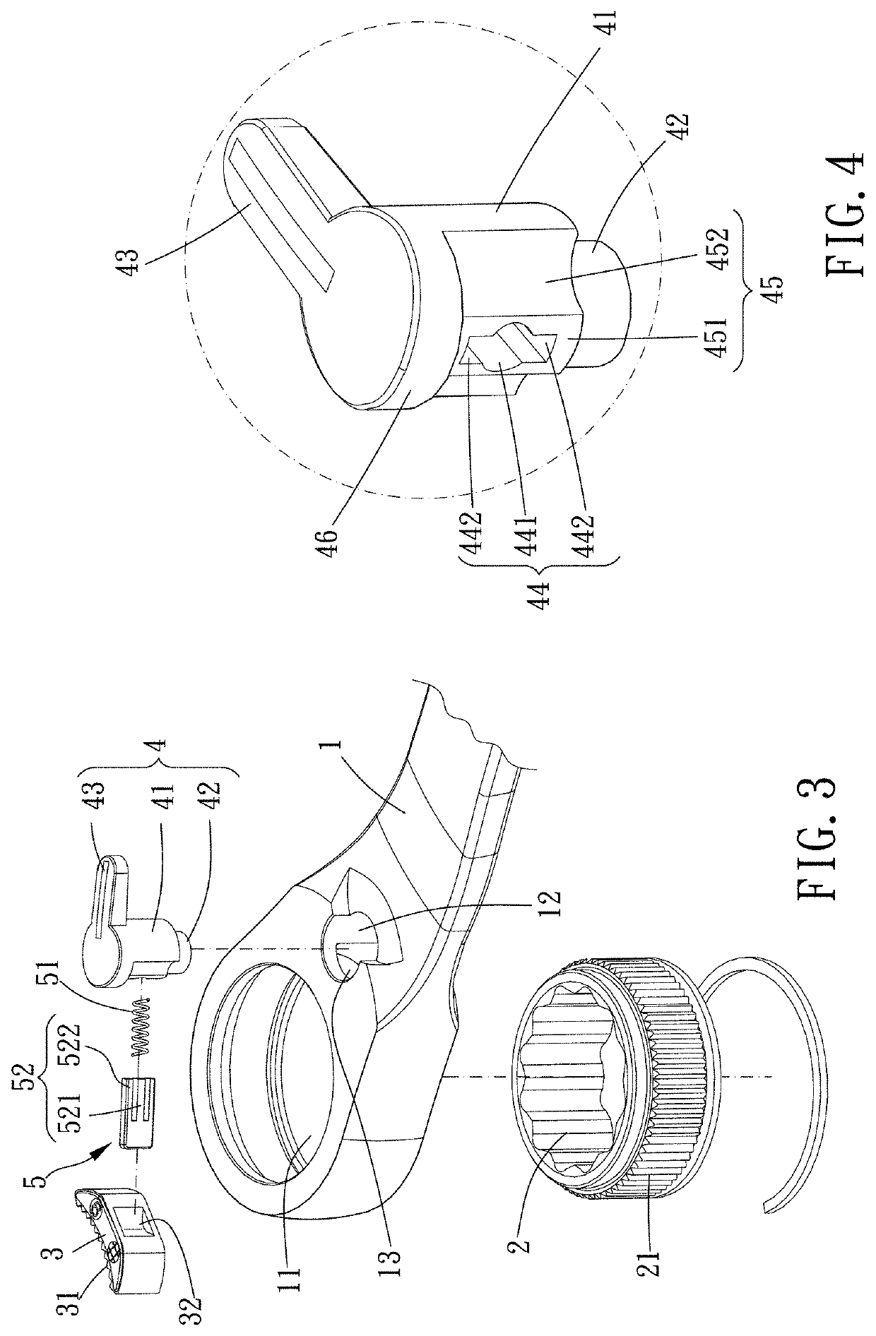
[0023]Please refer to FIGS. 1 to 6 for a preferable embodiment of the present invention. A ratchet wrench of the present invention includes a main body 1, a driving member 2, a restricting member 3, a switching member 4 and an elastic abutting assembly 5.

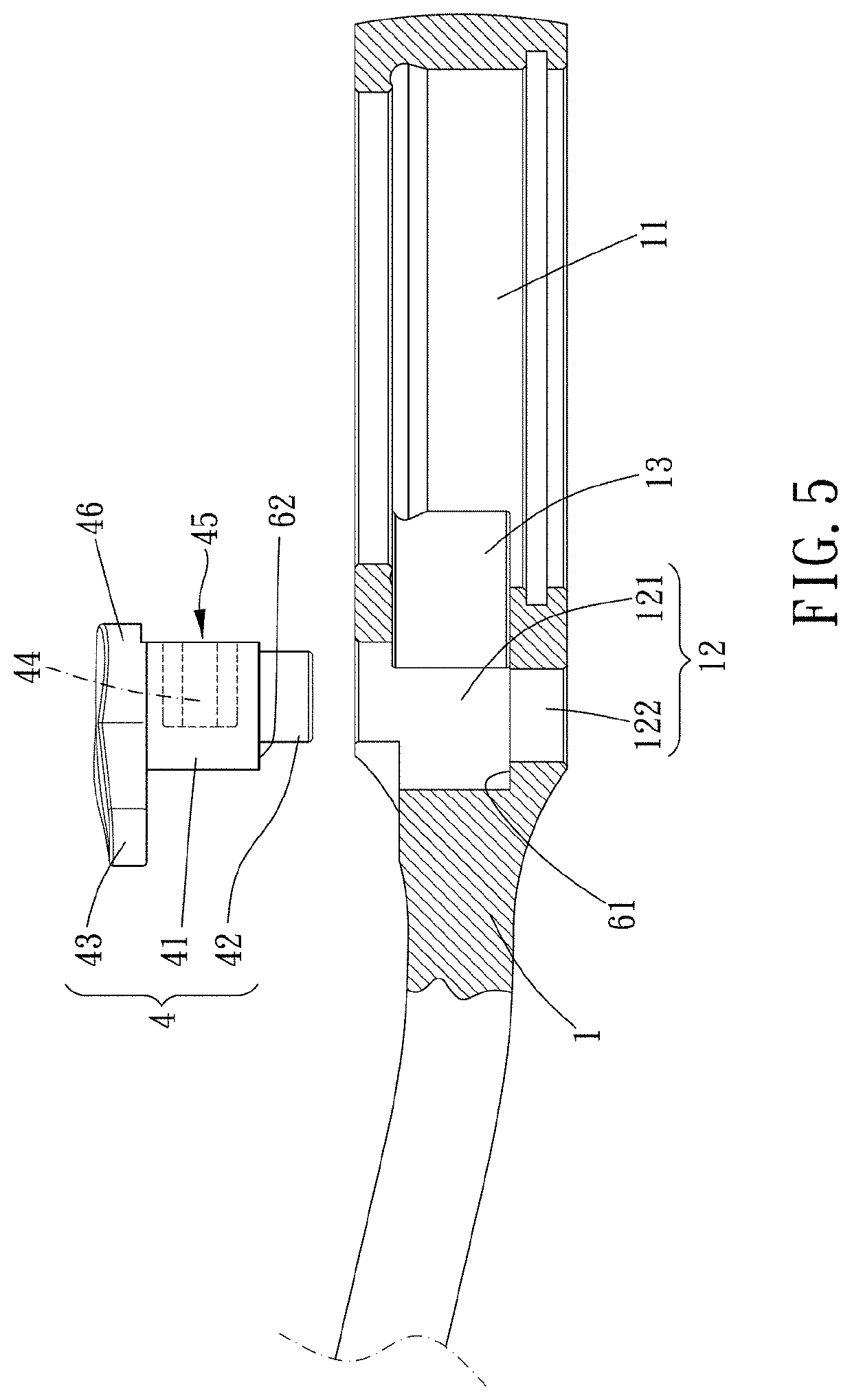
[0024]The main body 1 has a first receiving chamber 11, a second receiving chamber 12 being parallel to the first receiving chamber 11, and a third receiving chamber 13 which is communicated with the first receiving chamber 11 and the second receiving chamber 12. One end of the second receiving chamber 12 includes a larger diameter section121, and another end of the second receiving chamber 12 includes a small diameter section 122.

[0025]The driving member 2 is rotatably assembled within the first receiving chamber 11, and a first engaging portion 21 is disposed around a peripheral surface of the driving member 2. In this embodiment, the first engaging portion 21 includes a plurality of teeth, and an inner circumferential surface of ...


PUM


Abstract

A ratchet wrench is provided, including a main body, a driving member, a restricting member, a switching member and an elastic abutting assembly. The main body has a first receiving, chamber, a second receiving chamber and a third receiving chamber which is communicated with the first receiving chamber and the second receiving chamber. One end of the second receiving chamber is formed with a larger diameter section, and the other end of the second receiving chamber is formed with a small diameter section. The driving member is rotatably assembled within the receiving chamber. The restricting member is disposed in the third receiving chamber and limitable to a rotational direction of the driving member. The switching member is rotatably disposed within the second receiving chamber and includes a rotatable member and a projection which extends from the rotatable member. The rotatable member is received in the larger diameter section and the projection is received in the small diameter section. A bottom of the ratchet wrench of this invention is smoothly rotatable and the ratchet wrench effectively prevents the bottom from departing from the main body, which increase durability and efficiency.

Description

BACKGROUND OF THE INVENTIONField of the Invention[0001]The present invention relates to a hand tool, and more particularly to a ratchet wrench.Description of the Prior Art[0002]A conventional ratchet wrench disclosed in Taiwan patent number M520964 includes a main body assembled with a driving ratchet, a ratchet block and a switch. The switch is rotatably disposed on the main body, and a spring is disposed between the switch and the ratchet block so that the ratchet block has a tendency to normally bias the driving ratchet to restrict a rotational direction of the driving ratchet.[0003]However, the switch of the conventional ratchet wrench can sway when being switched so that the switch cannot be rotated smoothly. The switch may depart from the main body and result in breaking up into components, which influences efficiency of work.[0004]The present invention is, therefore, arisen to obviate or at least mitigate the above-mentioned disadvantages.SUMMARY OF THE INVENTION[0005]The mai...

Claims


Application Information

Patent Timeline
Patent Type & Authority Patents(United States)
IPC IPC(8): B25B13/46B25B23/00
CPCB25B13/463B25B13/46B25B23/0007
Inventor CHAN, YI-TUNG
Owner STANLEY CHIRO INT
Learn More