Airflow velocity measuring apparatus and airflow rate measuring apparatus
a technology of airflow velocity and measuring apparatus, which is applied in the direction of instruments, heat measurement, volume metering, etc., can solve the problems of difficult manufacturing, reduced measurement accuracy of gas flow rate, and high noise of measurement, so as to achieve high accuracy of measurement, reduce noise, and reduce the effect of nois
- Summary
- Abstract
- Description
- Claims
- Application Information
AI Technical Summary
Benefits of technology
Problems solved by technology
Method used
Image
Examples
first embodiment
; Airflow Velocity Measuring Apparatus 100
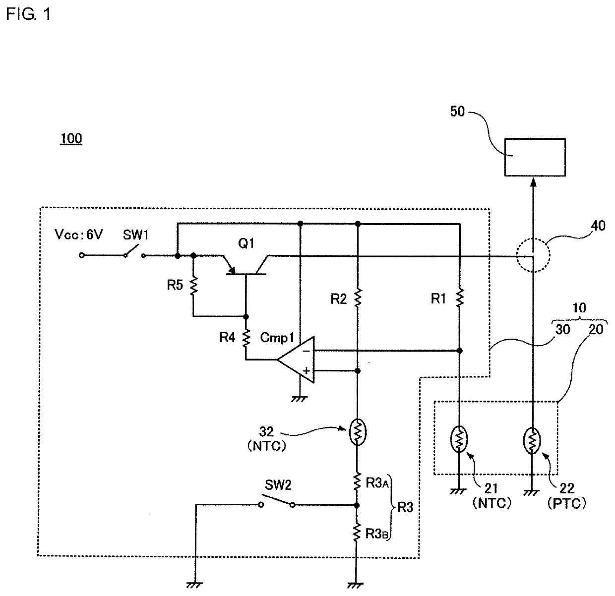
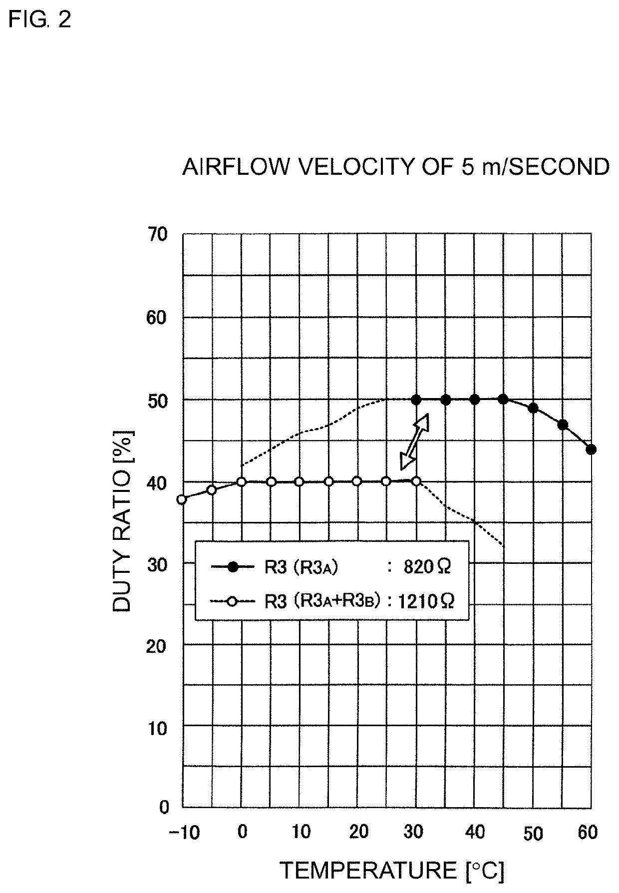
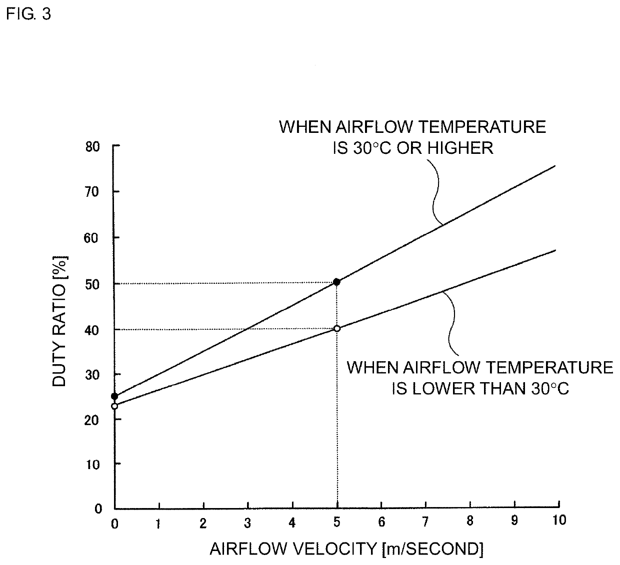
[0031]An airflow velocity measuring apparatus 100 according to a first embodiment is shown in FIG. 1.
[0032]Before completing the invention of this application, the inventor of this application has developed an airflow velocity measuring apparatus 1100A (see FIG. 7) as a reference outside the scope of the invention of this application. The airflow velocity measuring apparatus 1100A achieves high accuracy of measurement and has a simple structure and is easy to manufacture at low cost without requiring an expensive element, such as an A / D converter. In the airflow velocity measuring apparatus 1100A, however, measurement errors occur in the airflow velocity caused by a rise or a fall in the temperature of subject airflow.
[0033]To address this issue, the inventor of this application has made improvements in the airflow velocity measuring apparatus 1100A and developed an airflow velocity measuring apparatus 1100B (see FIG. 9) used as a reference ...
second embodiment
; Airflow Velocity Measuring Apparatus 200
[0122]An airflow velocity measuring apparatus 200 according to a second embodiment is shown in FIG. 4. FIG. 4 is an equivalent circuit diagram of the airflow velocity measuring apparatus 200.
[0123]The airflow velocity measuring apparatus 200 is an apparatus in which part of the configuration of the airflow velocity measuring apparatus 100 of the above-described first embodiment is changed. In the airflow velocity measuring apparatus 100, the second switch SW2 is provided between a ground and a node between the first and second divided resistor elements R3A and R3B. In the airflow velocity measuring apparatus 200, instead of the second switch SW2, a second switching element Q2 is disposed between a ground and a node between the first and second divided resistor elements R3A and R3B. In this embodiment, an NPN transistor is used as the second switching element Q2. However, the type of second switching element Q2 is not limited to an NPN transi...
third embodiment
; Airflow Velocity Measuring Apparatus 300
[0127]An airflow velocity measuring apparatus 300 according to a third embodiment is shown in FIG. 5. FIG. 5 is an equivalent circuit diagram of the airflow velocity measuring apparatus 300.
[0128]The airflow velocity measuring apparatus 300 is also an apparatus in which part of the configuration of the airflow velocity measuring apparatus 100 of the above-described first embodiment is changed. In the airflow velocity measuring apparatus 100, the second switch SW2 is provided between a ground and a node between the first and second divided resistor elements R3A and R3B. In the airflow velocity measuring apparatus 300, instead of the second switch SW2, a second comparator element Cmp2 is disposed.
[0129]A direct current of about 1.3 V is applied to the inverting input terminal − of the second comparator element Cmp2.
[0130]A node between the resistor elements R2 and R3 (first divided resistor element R3A) of the comparison voltage divider circui...
PUM
| Property | Measurement | Unit |
|---|---|---|
| airflow velocity measuring | aaaaa | aaaaa |
| temperature | aaaaa | aaaaa |
| resistance | aaaaa | aaaaa |
Abstract
Description
Claims
Application Information
 - R&D
- Intellectual Property
- Life Sciences
- Materials
- Tech Scout
- Unparalleled Data Quality
- Higher Quality Content
- 60% Fewer Hallucinations
Browse by: Latest US Patents, China's latest patents, Technical Efficacy Thesaurus, Application Domain, Technology Topic, Popular Technical Reports.
© 2025 PatSnap. All rights reserved.Legal|Privacy policy|Modern Slavery Act Transparency Statement|Sitemap|About US| Contact US: help@patsnap.com


