
Dual-material vacuum cup for a vacuum-based end effector

a vacuum-based, end-effector technology, applied in the direction of gripping heads, manipulators, manufacturing tools, etc., can solve the problems that vacuum-based end-effectors of known construction may not be able to sufficiently grasp flexible plastic bags or similar parcels in flexible packaging materials that may have a wrinkled or non-uniform surface, and achieve the effect of effectively grasping a target parcel

Active Publication Date: 2022-02-08
MATERIAL HANDLING SYST INC
View PDF17 Cites 4 Cited by
  • Summary
  • Abstract
  • Description
  • Claims
  • Application Information

AI Technical Summary

Benefits of technology

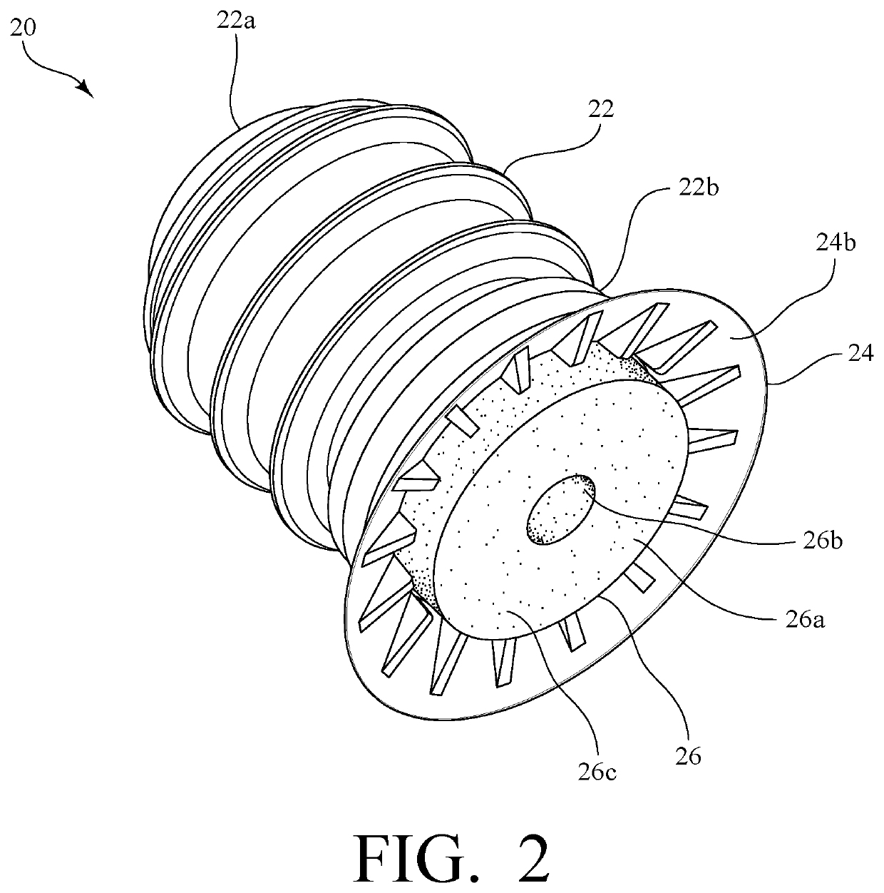
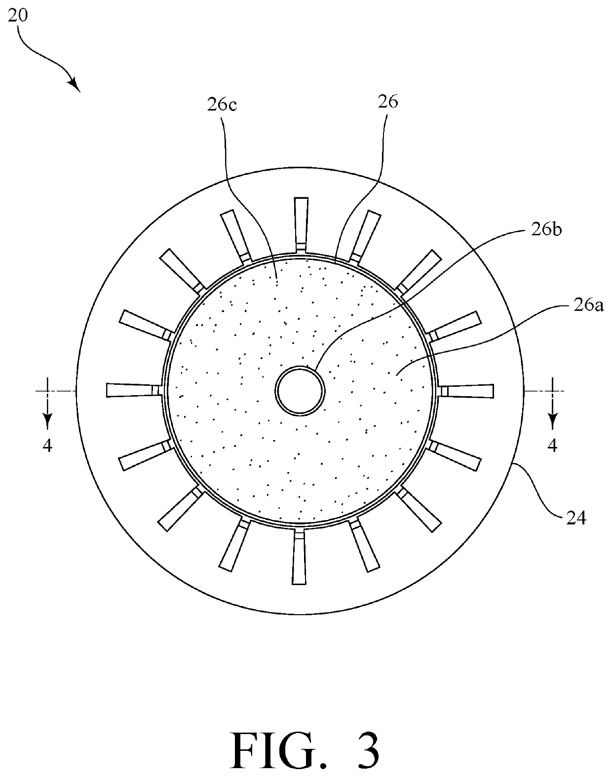
[0006]A dual-material vacuum cup for a vacuum-based end effector includes a bellows, a lip, and an insert. The bellows has a proximal end configured for connection to a vacuum-based end effector, where it is placed in fluid communication with a vacuum source. The bellows also has a distal end to which the lip is connected. The bellows defines a pathway along which a flow of air can travel, and the lip defines an opening in fluid communication with the pathway, such that air drawn through the opening defined by the lip subsequently travels through the bellows. The insert is connected to a distal end of the lip and is in fluid communication with the opening defined by the lip, so that air drawn through the insert subsequently passes through the opening and through the bellows. Thus, the vacuum cup can be placed in fluid communication with a vacuum source to provide a suction force which enables the vacuum cup to effectively grasp a target parcel.
[0007]To better enable the vacuum cup to engage parcels of various sizes and shapes and made of various materials, the lip is composed of a first material, and the insert is composed of a second material. In some embodiments, the lip is composed of an elastomeric material, such as silicone rubber, while the insert is composed of a foam material, such as a polyethylene or a polyurethane foam.

Problems solved by technology

Thus, within the sorting facility, there is often a complex system of conveyors and equipment that facilitates transport and sorting of the various parcels within the facility.
However, as the parcels moving through a given sorting facility have a number of different shapes and sizes and are in packaging ranging from rigid cardboard boxes to flexible plastic (“poly”) bags or other flexible materials, current end effectors are generally not capable of or are not readily configured to effectively and adequately grasp or engage each and every type of parcel.
For example, vacuum-based end effectors of known construction may be unable to sufficiently grasp flexible plastic (“poly”) bags or similar parcels in flexible packaging materials that may have a wrinkled or non-uniform surface.

Method used


Image

  • Dual-material vacuum cup for a vacuum-based end effector
  • Dual-material vacuum cup for a vacuum-based end effector
  • Dual-material vacuum cup for a vacuum-based end effector

Examples


Embodiment Construction

[0012]The present invention is a dual-material vacuum cup for vacuum-based end effectors that are used to engage parcels within a sorting or similar facility.

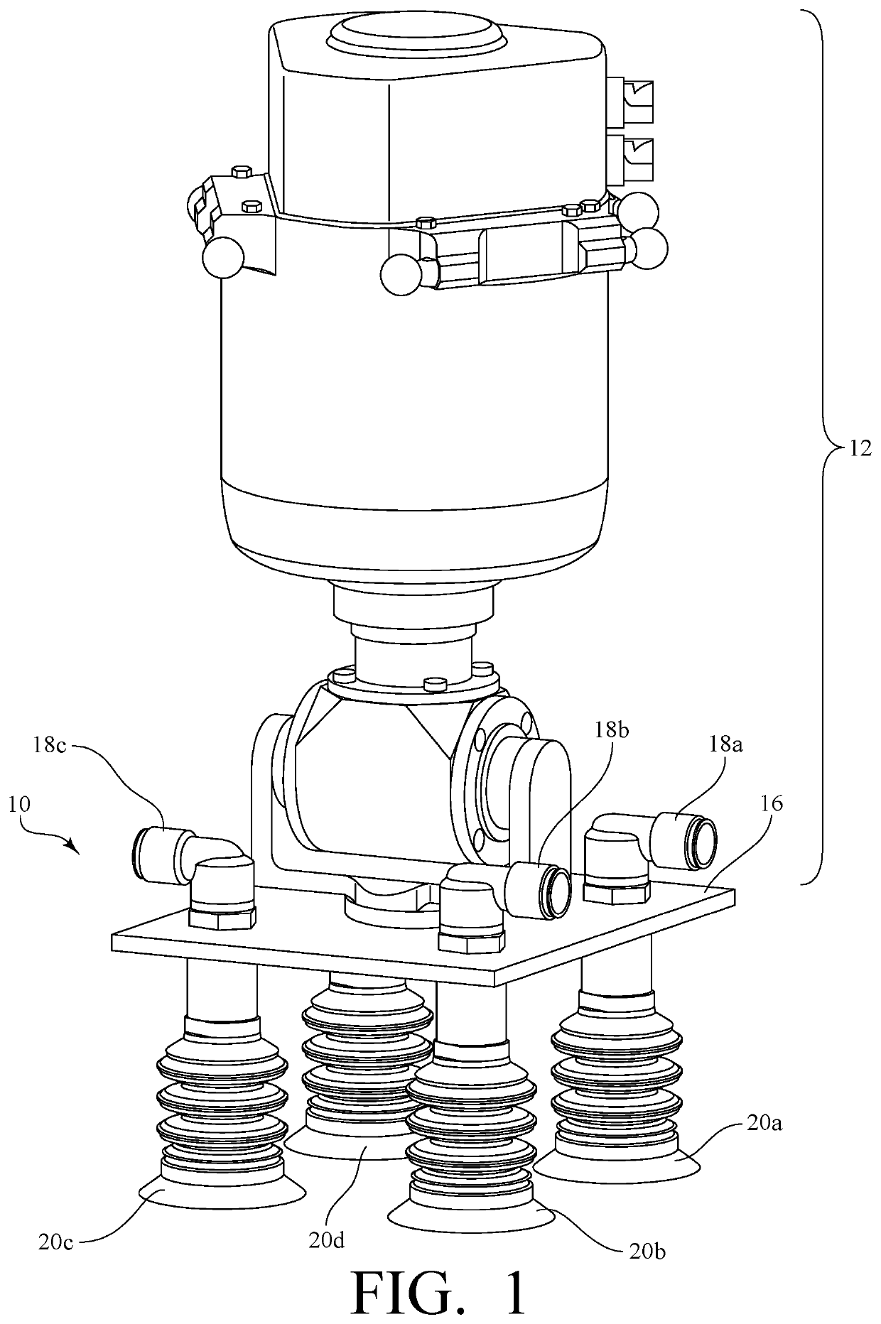
[0013]FIG. 1 is a perspective view of a vacuum-based end effector 10 for engaging parcels, including exemplary dual-material vacuum cups 20a, 20b, 20c, 20d made in accordance with the present invention, which is mounted to a portion of a robot 12. It should be appreciated that the portion of a robot 12 shown may be a component, such as a robotic arm, of a larger robot or robotic system, which is configured to move the end effector 10 toward a target parcel. For example, the portion of the robot 12 may be a component of a Delta P6 robot manufactured by Schneider Electric and available, for instance, from Advantage Industrial Automation of Duluth, Ga.

[0014]Referring still to FIG. 1, the end effector 10 includes a base plate 16 to which multiple vacuum cups 20a, 20b, 20c, 20d are mounted. In this particular embodiment, the end eff...


PUM


Abstract

A dual-material vacuum cup for a vacuum-based end effector includes a bellows having a proximal end configured for connection to the end effector and a distal end. The bellows also defines a pathway for a flow of air. A lip is connected to the distal end of the bellows, the lip defining an opening in fluid communication with the pathway for the flow of air. An insert is then connected to a distal end of the lip, and the insert is in fluid communication with the opening defined by the lip. To engage parcels of various dimension and construction, the lip is composed of a first material (such as silicone rubber or another elastomeric material), while the insert is comprised of a second material (such as a foam material).

Description

CROSS-REFERENCE TO RELATED APPLICATIONS[0001]The present application claims priority to U.S. Patent Application Ser. No. 62 / 807,136 filed on Feb. 18, 2019, the entire disclosure of which is incorporated herein by reference.BACKGROUND OF THE INVENTION[0002]The present invention relates to vacuum-based end effectors that are used to engage parcels within a sorting or similar facility.[0003]In a sorting facility for parcels, various parcels are unloaded from trucks or other vehicles at unloading locations, sorted, and then loaded onto trucks or other vehicles at loading locations for delivery to the intended recipients. Thus, within the sorting facility, there is often a complex system of conveyors and equipment that facilitates transport and sorting of the various parcels within the facility.[0004]One such piece of equipment is an end effector, which can be attached to a robot and maneuvered to grasp or engage the parcels that are placed on the conveyers of the systems. In this regard...

Claims


Application Information

Patent Timeline
Patent Type & Authority Patents(United States)
IPC IPC(8): B25J15/06B25J15/00
CPCB25J15/0691B25J15/0057B25J15/0683
Inventor DOUGLAS, JOSIAHSTURM, DEREK ROBERTCALDWELL, II, DAVID W.
Owner MATERIAL HANDLING SYST INC
Learn More