Method for adjusting an adjustment device of a wind power plant

a technology of wind power plants and adjustment devices, which is applied in the direction of engine control, motors, engine fuctions, etc., can solve the problems of uncontrolled adjustment movement of residual braking torque, complicated adjustment of adjustment devices, and many revolutions of drive shafts of drive motors, etc., to achieve good and secure adjustment

Active Publication Date: 2022-01-18
B&R IND AUTOMATION GMBH
View PDF5 Cites 0 Cited by
  • Summary
  • Abstract
  • Description
  • Claims
  • Application Information

AI Technical Summary

Benefits of technology

[0008]In addition, the position control also ensures that the drive axles brake automatically when high wind tries to accelerate the movable part of the wind power plant in the direction of rotation. This is particularly advantageous in an embodiment where the total torque of the drive axles is directed against the movement, if the wind becomes so strong that the wind accelerates the movable part against the braking effect, the other drive axles then provide braking assistance due to the position control. This prevents an uncontrolled movement of the movable part due to the wind.
[0009]It is advantageous if during the tensioning a desired total torque is set as the sum of the individual drive torques of the drive axles, in particular, if the total torque counteracts the desired movement of the movable part. The total torque thus has a braking effect and acts as damping during the adjustment.
[0012]It is particularly advantageous if one drive axle is defined as the master drive axle and the other drive axles follow the movement of the master drive axle. This can ensure that the relative positions of the drive axles with respect to each other are maintained particularly precisely because the slave drive axles follow the actual movement of the master drive axles.
[0013]For the adjustment, it is particularly advantageous if the drive axles are re-tensioned between the tensioning and the start of the adjustment, as this compensates for any undesirable changes in the tensioning state before the adjustment, thereby ensuring a particularly good and secure adjustment.
[0020]According to embodiments, the tensioning may be maintained by maintaining the relative positions of the drive motors with respect to each other reached during tensioning of the drive axles. Further, during tensioning, a desired total torque can be set as the sum of the individual drive torques of the drive axles. The total torque counteracts the desired movement of the movable part.

Problems solved by technology

This may require many revolutions of the drive shaft of the drive motor.
For this reason, the adjustment of the adjustment device, in particular when under wind load, is more complicated than it appears.
To prevent this, the adjustment brake is not opened fully in wind power plants having adjustment brakes, such that a residual braking torque counteracts an uncontrolled adjustment movement.
However, this produces wear on the adjustment brake and leads to excessive noise (squeaking), due to the partially released adjustment brake, which can also lead to problems with the certification of the wind turbine.
The disadvantage in this case is that the applied braking torque is fixed.
At low wind loads, this braking torque is usually too high, which makes this type of adjustment inefficient in terms of the energy used.
At high wind loads, the braking torque can still be overcome by the external load when the adjustment device is adjusted, and the movable part of the adjustment device may be moved in an uncontrolled manner.
Due to the rotation speed control or torque control, the tensioning would be released and control over the movement of the movable part (e.g. the nacelle) can be lost.

Method used


Image

  • Method for adjusting an adjustment device of a wind power plant
  • Method for adjusting an adjustment device of a wind power plant
  • Method for adjusting an adjustment device of a wind power plant

Examples


Embodiment Construction

[0035]The particulars shown herein are by way of example and for purposes of illustrative discussion of the embodiments of the present invention only and are presented in the cause of providing what is believed to be the most useful and readily understood description of the principles and conceptual aspects of the present invention. In this regard, no attempt is made to show structural details of the present invention in more detail than is necessary for the fundamental understanding of the present invention, the description taken with the drawings making apparent to those skilled in the art how the several forms of the present invention may be embodied in practice.

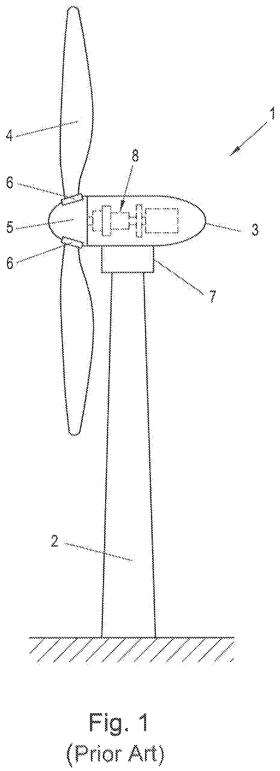
[0036]The present invention is described, without restricting the generality, using the example of an azimuth adjustment mechanism (wind direction tracking mechanism 7) for the nacelle 3 of a wind power plant 1. Of course, the invention can also be applied to other adjustment devices for a movable part of a wind power pla...


PUM


Abstract

In order to be able to better control the movement of the movable part of the wind power plant during an adjustment, the drive axles are tensioned against each other prior to the adjustment by rotating at least one drive axle relative to the other drive axles, and the drive axles are rotated together in the same direction of rotation during the adjustment the drive axles while maintaining the tensioning of the drive axles by way of a position control, until the desired end position of the movable part is reached.

Description

CROSS-REFERENCE TO RELATED APPLICATIONS[0001]The present application claims priority under 35 U.S.C. § 119(a) of Europe Patent Application No. EP 191 59 737.6 filed Feb. 27, 2019, the disclosure of which is expressly incorporated by reference herein in its entirety.BACKGROUND1. Field of the Invention[0002]The present invention relates to a method for adjusting an adjustment device of a wind power plant, by which a movable part of the wind power plant is rotated, wherein the adjustment device includes at least two drive axles, each having a drive motor and which are mechanically coupled to the movable part. The invention also relates to a wind power plant having such an adjustment device.2. Discussion of Background Information[0003]Wind power plants generally have adjustment devices for various movable parts of the wind power plant, such as a rotor blade adjustment mechanism or an azimuth adjustment mechanism, in order to adapt the wind power plant to changing wind conditions (windsp...

Claims


Application Information

Patent Timeline
Patent Type & Authority Patents(United States)
IPC IPC(8): F03D7/02F03D15/00
CPCF03D7/022F03D7/0204F03D15/00F03D7/0224F05D2270/62F05B2260/79Y02E10/72F05B2260/40
Inventor KRONBERGER, PETERFORTHUBER, FRIEDRICHFESTERLING, ALEXANDER
Owner B&R IND AUTOMATION GMBH
Why Eureka
Try Eureka