Stocker

a stocker and control panel technology, applied in the field of stockers, can solve the problems of controlling panel influence on the container, and achieve the effects of reducing preventing or preventing temperature rise, and blocking or suppressing heat transfer

Active Publication Date: 2022-01-11
MURATA MASCH LTD
View PDF4 Cites 0 Cited by
  • Summary
  • Abstract
  • Description
  • Claims
  • Application Information

AI Technical Summary

Benefits of technology

[0004]Preferred embodiments of the present invention provide stockers each capable of reducing influences of heat on articles (containers or contents of the containers) in a storage area by effectively blocking or suppressing heat transfer from a control panel to the storage area.
[0007]According to preferred embodiments of the present invention, since the first thermal insulation layer on the wall side of the control panel storage and the second thermal insulation layer on the storage area side of the control panel storage are provided, it is possible to reduce or prevent temperature increases on the wall side and the storage area side of the control panel storage, respectively. In the configuration in which the fan on the wall draws in outside air and introduces the outside air into the storage area, the air, the temperature of which has risen as a result of the heat having been transferred from the wall side of the control panel storage to the outside, may be drawn in by another fan that is also provided on the same wall side. However, by providing the first thermal insulation layer, it is possible to block or suppress transfer of heat from the control panel storage to the wall side, and to reduce or prevent the temperature rise in the air which has been introduced into the storage area by the fan. This configuration enables reduction in the influence of heat on articles in a storage area by blocking or suppressing heat transfer from the control panel to the storage area.
[0008]In those cases where the first thermal insulation layer is a ventilation layer which allows air to flow therethrough, influence of the heat generated in the control panel is able to be reliably reduced by effectively blocking or suppressing heat transfer in the first thermal insulation layer. In those cases where the ventilation layer is a duct extending in a vertical direction, and the duct includes a first vent in one of an upper portion and a lower portion of the stocker to communicate the outside of the wall with the inside of the duct, a second vent in the other of the upper portion and the lower portion of the stocker to communicate the inside of the duct with the inside of the control panel storage, and a second fan arranged laterally on the opposite side of the storage area of the control panel storage, and which draws in the air in the control panel storage and blows the air out to the outside of the stocker, the second fan creates an air flow in the duct and releases the heat inside the control panel storage to the outside, so that the influence of generated heat from the control panel is able to be reliably reduced.
[0009]In cases where the second fan is above the fan, it is possible to prevent the air released from the second fan to the outside of the stocker from being introduced into the storage area in the stocker again by the fan. In cases where the control panel storage is provided in vertically multiple layers and the second fan is provided for each of these layers, the inside air is able to be individually released to the outside from the control panel storage provided in each layer, and heat transfer from each control panel storage to the storage area is able to be effectively blocked or suppressed. In cases where the second thermal insulation layer is a ventilation layer to allow air to flow therethrough or is a thermal insulation material, since the ventilation layer is provided at the boundary between the control panel storage and the storage area, transfer of the heat to the storage area is able to be appropriately blocked or suppressed.

Problems solved by technology

In such a stocker, there is a possibility that heat generated in the control panel may influence the container stored in the storage area or the contents of container.
However, the heat of the control panel may still be transferred to the storage area from parts other than the boundary portion between the control panel storage and the storage area, and when heat is transferred to the storage area, it may influence the container placed in the storage area or the contents of the container.

Method used


Image

  • Stocker
  • Stocker
  • Stocker

Examples


Embodiment Construction

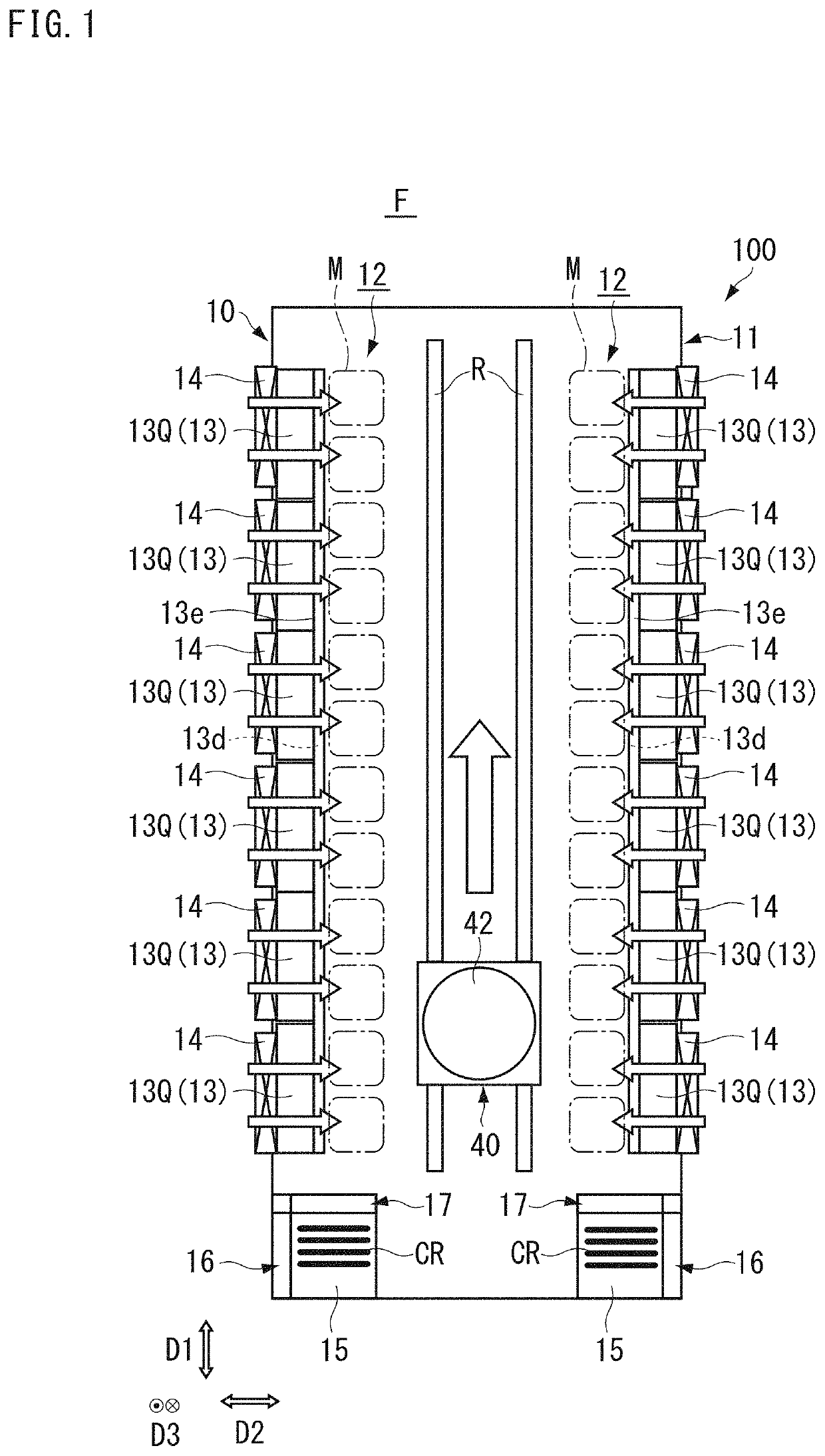
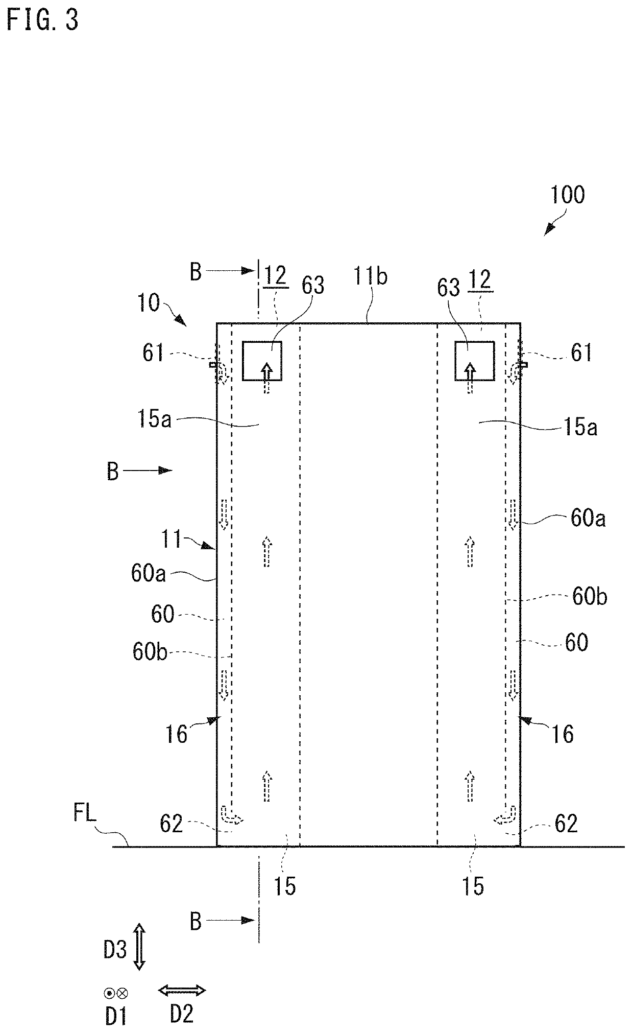
[0018]The following describes preferred embodiments of the present invention with reference to the drawings. However, the present invention is not limited to the preferred embodiments described herein. In the drawings, scale is changed as necessary to illustrate the preferred embodiments, such as by enlarging or by emphasizing an element or portion. Also, in each figure, a horizontal direction (the direction parallel to floor FL), which is a longitudinal direction of storage area 12 described later (or a traveling direction of a transporter 40 described later), is referred to as a first direction D1, a horizontal direction, which is a direction orthogonal to the first direction D1, is referred to as a second direction D2, and a vertical direction perpendicular to floor FL is referred to as a third direction D3.

[0019]FIG. 1 and FIG. 2 are diagrams showing an example of a stocker 100 according to a preferred embodiment of the present invention. FIG. 1 is a cross-sectional view of the ...


PUM


Abstract

A stocker includes a wall that separates an inside and an outside of the stocker, a storage area on an inner side of the wall and in which articles are stored, a fan on the wall to draw in outside air and introduce the outside air into the inside of the stocker, a control panel storage provided on the inner side of the wall and laterally to the storage area to store a control panel, a first thermal insulation layer on a wall side of the control panel storage, and a second thermal insulation layer on a storage area side of the control panel storage.

Description

BACKGROUND OF THE INVENTION1. Field of the Invention[0001]The present invention relates to a stocker.2. Description of the Related Art[0002]A stocker is installed in a semiconductor manufacturing factory or the like in order to store a plurality of containers (articles) for accommodating reticles, semiconductor wafers or the like. The stocker has a wall that separates an inside and an outside of the stocker; a storage area which is arranged on an inner side of the wall and in which articles are stored; and a control panel storage which is arranged on an outer side of the wall and which stores a control panel which controls the operation of each part. In such a stocker, there is a possibility that heat generated in the control panel may influence the container stored in the storage area or the contents of container. For this reason, there is known a configuration in which a thermal insulation layer is arranged on the storage area side of the control panel storage so that the heat of ...

Claims


Application Information

Patent Timeline
Patent Type & Authority Patents(United States)
IPC IPC(8): H01L21/677B65G1/02H01L21/673
CPCH01L21/67769B65G1/02H01L21/67379H01L21/67383H01L21/67389B65G1/00H01L21/673H01L21/67017
Inventor KUSAMA, YUSUZUKI, TORU
Owner MURATA MASCH LTD
Why Eureka
Try Eureka