
Device and method for switching time compensation on the valve block

a valve block and switching time compensation technology, applied in the field of devices and a method for reshaping plastic parisons into plastic, can solve the problems of reducing the consistent quality of bottles, unable to achieve pure electrical actuation, and unable to ensure constant and consistent switching tim

Active Publication Date: 2022-01-11
KRONES AG
View PDF10 Cites 0 Cited by
  • Summary
  • Abstract
  • Description
  • Claims
  • Application Information

AI Technical Summary

Benefits of technology

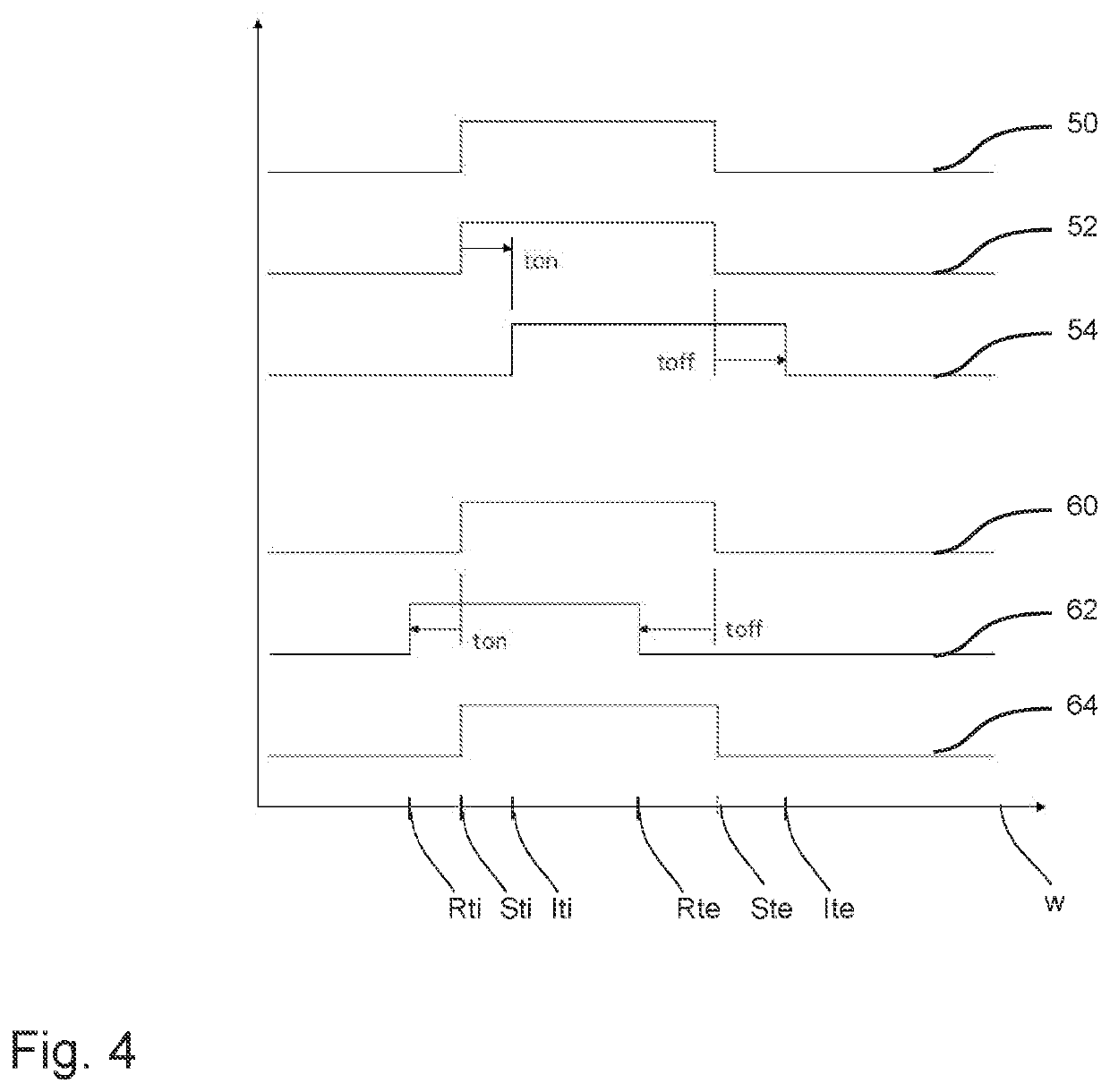
The patent is about improving the process of blow molding by controlling the switching of valves to achieve a specific state at a specific time. This is done individually for each valve to compensate for variations in the valve's performance. By measuring the time it takes to reach the desired state, the control system can adjust the valves to optimize the process and achieve consistent quality. The patent also describes a regulating device for each valve that can compensate for slow drifting or variations in the flow of the medium. Overall, this technology allows for better utilization of the process time and achieves higher quality containers.

Problems solved by technology

A purely electrical actuation is not possible, since the switching currents would be too great for the digital output modules.
The devices and methods which are currently known from the conventional art give rise to the disadvantage that in the case of pneumatic valves no constant and consistent switching time can be ensured, since they are subject to a certain variation.
All these factors reduce the consistent quality of the bottles.
However, in contrast to an electrically controlled valve device, disadvantageously due to the pneumatic mode of operation of the control an (additional) “reaction time” or trigger time occurs which delays the connection of the valve device from the time of the electrical switching signal for connection of the pilot control device until the required state of the valve device is reached.
Furthermore, this clean room is delimited by means of at least one wall relative to unsterile surroundings.

Method used


Image

  • Device and method for switching time compensation on the valve block
  • Device and method for switching time compensation on the valve block
  • Device and method for switching time compensation on the valve block

Examples


Embodiment Construction

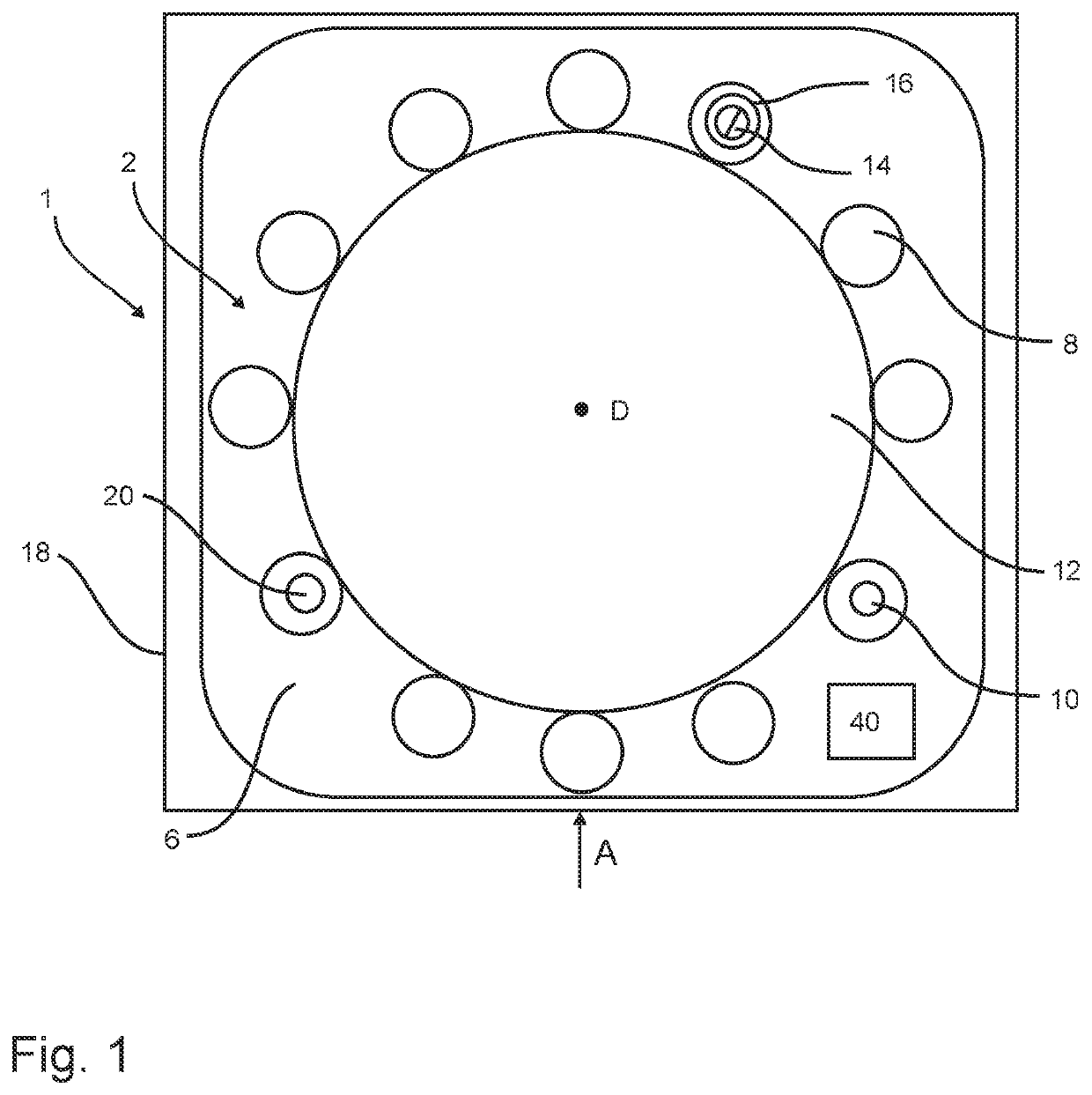
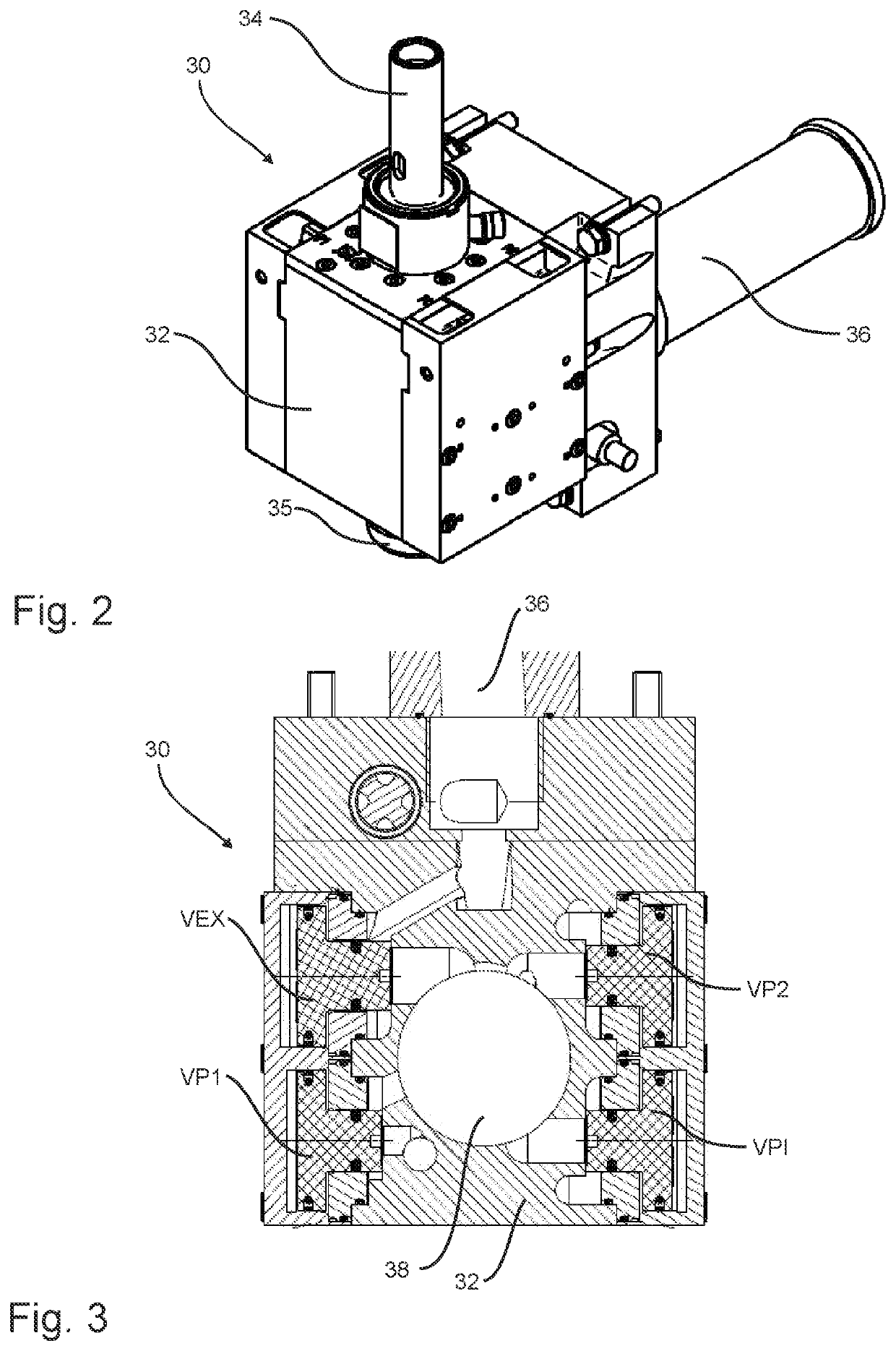
[0044]FIG. 1 shows a schematic representation of a device 1 for reshaping plastic parisons 10 into plastic containers 20. In this case the plastic parisons 10 are fed to the individual reshaping stations or blow moulding stations 8 and are expanded to form plastic containers 20, while they are being transported by a transport device 2. After this expansion the plastic containers 20 are removed from the device 1 again. For this purpose, a feed starwheel can be provided which delivers the plastic parisons to the machine 1 and also a discharge device, in particular likewise a transport starwheel, which discharges the finally expanded containers 20 from the device 1. The device 1 has a station support 12 on which a plurality of blow moulding stations 8 are arranged. In this case this station support may be for example, as shown in FIG. 1, a blow moulding wheel which is rotatable with respect to an axis of rotation D (which here extends perpendicular to the drawing plane and thus vertica...


PUM

PropertyMeasurementUnit
pressuresaaaaaaaaaa
pressureaaaaaaaaaa
pressureaaaaaaaaaa

Abstract

Provided is a device for reshaping plastic parisons into plastic containers, including a plurality of blow moulding stations each having blow mould devices which form a cavity, inside which the plastic parisons can be reshaped into plastic containers, and including at least one application device by which a flowable medium can be applied to the plastic parisons for expansion thereof, and at least one valve device which is arranged between at least one pressure reservoir and at least one application device and by which the supply and / or removal of the flowable medium, in particular under high pressure, in particular the blowing pressure and / or volume flow thereof, to the application device can be influenced or controlled.

Description

CROSS-REFERENCE TO RELATED APPLICATIONS[0001]This application claims priority to PCT Application No. PCT / EP2018 / 066704, having a filing date of Jun. 22, 2018, based on German Application No. 10 2017 114 138.3, having a filing date of Jun. 26, 2017, the entire contents both of which are hereby incorporated by reference.FIELD OF TECHNOLOGY[0002]The following relates to a device and a method for reshaping plastic parisons into plastic containers, comprising a plurality of blow moulding stations which each have blow moulding means or a blow mold, which form a cavity inside which plastic parisons can be reshaped into plastic contains.BACKGROUND[0003]Devices and methods for reshaping plastic parisons into plastic containers have been known for a long time from the conventional art. Usually for each blow moulding station an application device is provided, by means of which a flowable medium can be applied to the plastic parisons for expansion thereof. In this case the flowable medium is fe...

Claims


Application Information

Patent Timeline
Patent Type & Authority Patents(United States)
IPC IPC(8): B29C49/78B29C49/06B29C49/12B29C49/42B29C49/58
CPCB29C49/06B29C49/783B29C49/12B29C49/4289B29C2049/5803B29C2949/7889B29C2949/78537B29C2949/78554B29C2949/78621B29C49/78B29C2049/023B29C49/58
Inventor FINGER, DIETERHUETTNER, GERALD
Owner KRONES AG
Learn More