
Steering control system

a control system and steering technology, applied in the direction of mechanical steering, electrical steering, vehicle components, etc., can solve problems such as controlling the reaction torque, and achieve the effects of reducing the steering angle, and solving the driver's discomfor

Active Publication Date: 2022-01-04
TOYOTA JIDOSHA KK +2
View PDF7 Cites 1 Cited by
  • Summary
  • Abstract
  • Description
  • Claims
  • Application Information

AI Technical Summary

Benefits of technology

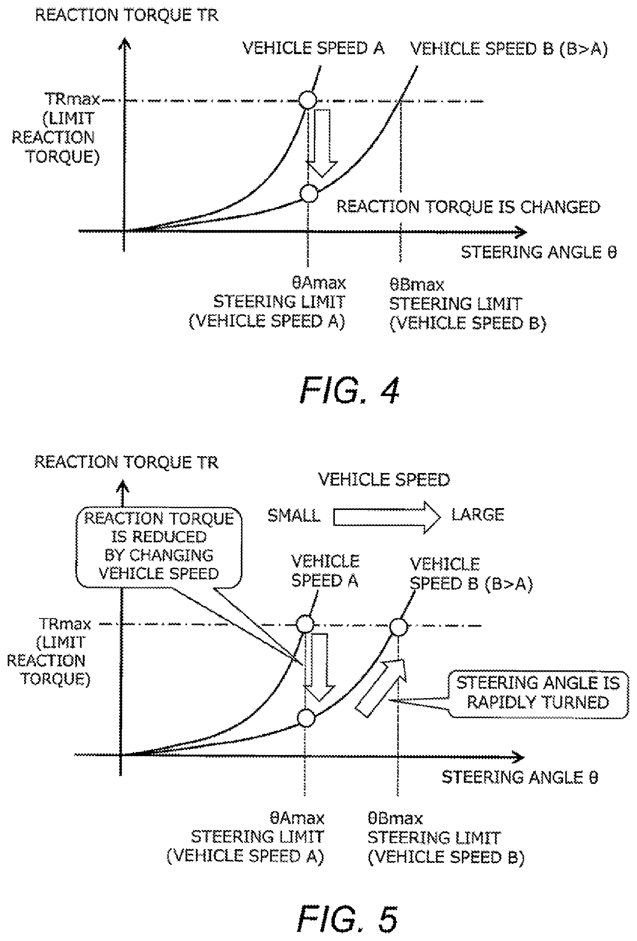
The present invention aims to provide a steering control system that can prevent sudden changes in reaction torque when the steering angle of a steer-by-wire vehicle is reached to its steering limit. This system can maintain the desired steering angle even if the vehicle's state changes, such as when it accelerates or decelerates. This helps to reduce discomfort for the driver and ensures safe driving.

Problems solved by technology

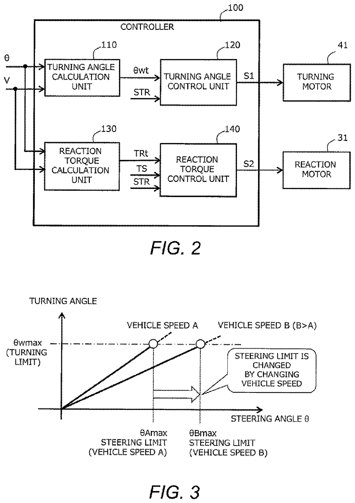
However, when the steering angle ratio characteristic changes, a steering limit of the steering corresponding to the turning limit at which the turning angle becomes the maximum changes.
As described above, in steering control of a steer-by-wire vehicle in which the steering angle ratio characteristic can be adjusted according to the state of the vehicle, there is a problem in controlling the reaction torque when the state of the vehicle changes at the steering limit.

Method used


Image

  • Steering control system
  • Steering control system
  • Steering control system

Examples


first embodiment

1. First Embodiment

1-1. Steering Control System

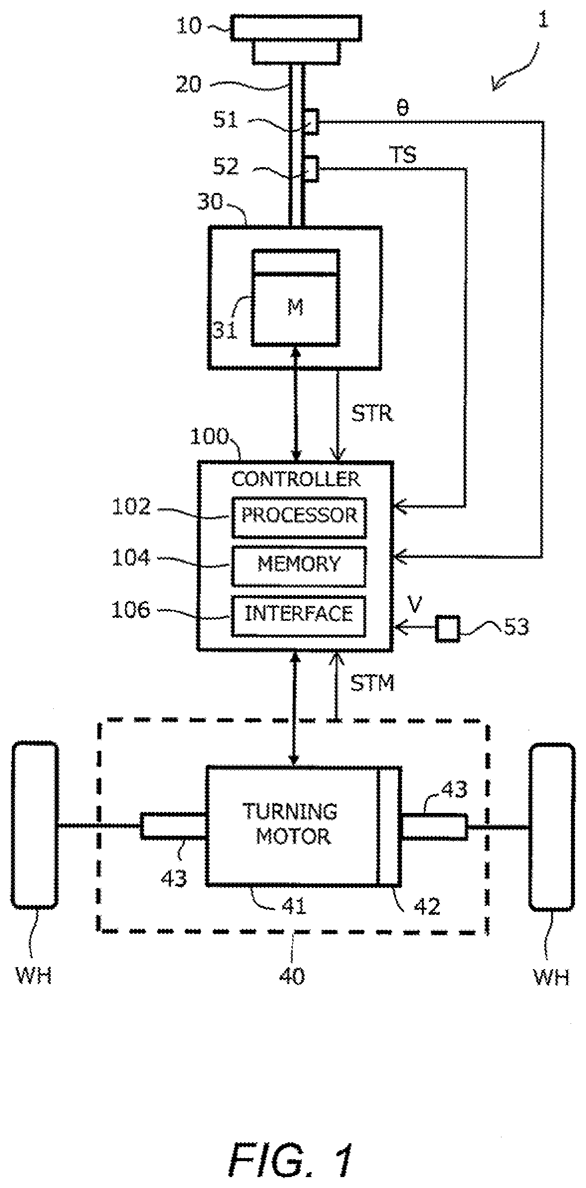
[0032]FIG. 1 is a block diagram schematically showing a configuration example of a steering control system according to the present embodiment. The steering control system 1 is mounted on a vehicle, and turns wheels WH of the vehicle by a steer-by-wire system. That is, the steering control system 1 realizes a steer-by-wire vehicle.

[0033]In the example shown in FIG. 1, the steering control system 1 includes a steering wheel 10, a steering shaft 20, a reaction force generating device 30, a turning device 40, a group of sensors 51 to 53, and a controller 100.

[0034]The steering wheel 10 is an operating member used by a driver for steering. The steering wheel 10 is also called a “steering 10”. The steering shaft 20 is connected to the steering wheel 10 and rotates together with the steering wheel 10.

[0035]The reaction force generating device 30 applies a reaction torque TR to the steering wheel 10 by operation of a reaction force motor 31. T...

second embodiment

2. Second Embodiment

2-1. Features of Second Embodiment

[0064]The steering control system of the second embodiment is characterized in that, when the vehicle speed changes (e.g., accelerates) from the vehicle speed A to the vehicle speed B (e.g., vehicle speed B>vehicle speed A) at the steering limit, the reaction torque adjustment process is performed to gradually reduce the reaction torque. The configuration of the steering control system of the second embodiment is the same as that of the steering control system 1 of the first embodiment. The basic idea of the turning angle control and the reaction torque control is the same as that of the first embodiment. Description overlapping with that of the first embodiment will be omitted as appropriate.

[0065]FIG. 9 is a diagram for explaining the reaction torque adjustment process according to the second embodiment. FIG. 10 is a time chart showing changes in the vehicle speed and the steering angle in the reaction torque adjustment process...


PUM


Abstract

A steering control system includes a steering-motor for turning wheels, a reaction-force-motor for applying a reaction torque to a steering of the vehicle, and a controller. The controller calculates a turning angle based on a first-characteristic representing a relationship of the turning angle to a steering angle, and calculates a reaction torque based on a second-characteristic representing a relationship of a reaction torque to the steering angle. The controller changes the first-characteristic from a characteristic corresponding to a first-state to a characteristic corresponding to a second-state in response to a change in the state of the vehicle from the first-state to the second-state. The controller maintains the second-characteristic at the characteristic corresponding to the first-state when the state of the vehicle changes from the first-state to the second-state in the case where the steering angle is steered to a steering limit corresponding to an upper limit of the turning angle.

Description

CROSS-REFERENCE TO RELATED APPLICATION[0001]The present application is based on, and claims priority from, Japanese Patent Application Serial Number 2019-057056, filed on Mar. 25, 2019, the disclosure of which is hereby incorporated by reference herein in its entirety.BACKGROUNDField[0002]The present disclosure relates to a steering control system, and more particularly, to a steering control system for a steer-by-wire vehicle.Background Art[0003]Japanese Patent Application Laid-Open No. 2018-047784 discloses a technique relating to a steering control apparatus for performing processing for avoiding that a steering operated so that a steering angle exceeds an upper limit value. In this technique, when the magnitude of the maximum value of the turning angle of the wheel or the steering angle of the steering becomes equal to or larger than the limit start threshold value, the reaction force actuator is operated to rapidly increase the limiting reaction force for limiting further incre...

Claims


Application Information

Patent Timeline
Patent Type & Authority Patents(United States)
IPC IPC(8): B62D5/00B62D6/02B62D15/02B62D5/04B62D6/00
CPCB62D5/005B62D5/0463B62D5/0466B62D6/002B62D6/02B62D15/021B62D6/00B62D6/008B62D6/005
Inventor MORINO, TETSUYAFURUKURA, TOSHIYAKUDO, YOSHIO
Owner TOYOTA JIDOSHA KK
Learn More