
Interface ultrasonic reflectivity-pressure relation curve establishment method and loading testbed

a technology of ultrasonic reflectivity and relation curve, applied in the field of ultrasonic detection, can solve the problems of difficult analysis of measurement, less accurate final test results, and generation of errors, so as to reduce the errors caused by measurement, the effect of understanding more accurately and reducing the effect of movement and the lik

Active Publication Date: 2021-12-21
DALIAN UNIV OF TECH
View PDF8 Cites 0 Cited by
  • Summary
  • Abstract
  • Description
  • Claims
  • Application Information

AI Technical Summary

Benefits of technology

The present invention provides a method and apparatus for accurately detecting pressure on an ultrasonic reflectivity film. This is important because existing methods have limitations in accurately measuring pressure and can produce errors. The new method uses multiple collections at the same point to take an average, resulting in a more accurate ultrasonic reflectivity-pressure relation curve and higher detection precision.

Problems solved by technology

A junction surface force distribution detecting method disclosed in related patents mostly uses a pressure-sensitive film as a means for measuring the contact pressure distribution within the contact interface, but the pressure-sensitive film itself has changed the interface condition, and finally it is difficult to analyze the measurement result.
To some extent, an error will be generated during curve construction, which makes the final test result less accurate.
For the loading testbed, most of the existing loading test pieces are of a holistic form, followed by the problems such as large volume, waste of materials and the like, and are relatively high in cost especially for test pieces such as titanium alloy as a detection material.
At the same time, an eccentric load caused by a linear movement error during loading can not be effectively processed, and a certain amount of error is caused to the detection result.

Method used


Image

  • Interface ultrasonic reflectivity-pressure relation curve establishment method and loading testbed
  • Interface ultrasonic reflectivity-pressure relation curve establishment method and loading testbed
  • Interface ultrasonic reflectivity-pressure relation curve establishment method and loading testbed

Examples


Embodiment Construction

[0056]To make the objectives, technical solutions and advantages of the embodiments of the present invention clearer, the technical solutions in the embodiments of the present invention will be described clearly and completely with reference to the accompanying drawings in the embodiments of the present invention. Apparently, the described embodiments are a part, but not all of the embodiments of the present invention. All other embodiments obtained by an ordinary person skilled in the art based on the embodiments of the present invention without paying creative labor shall fall within the protection scope of the present invention.

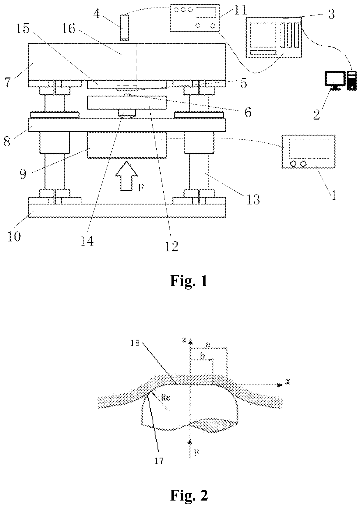
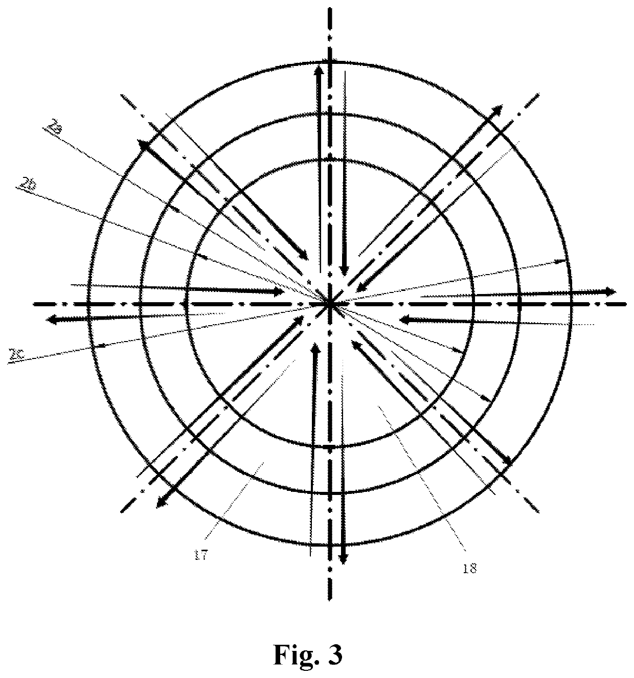
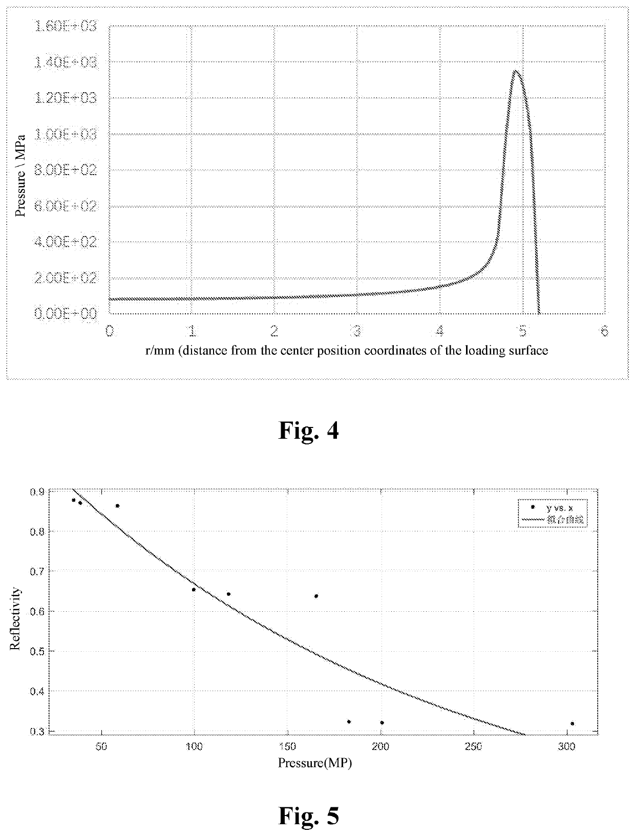
[0057]As shown in FIGS. 1 to 5, an interface ultrasonic reflectivity-pressure relation curve establishment method. This method is implemented by a loading testbed for the interface ultrasonic reflectivity-pressure relation curve establishment method. The loading testbed comprises a force displayer 1, a control terminal 2, an oscilloscope 3, an immersion ul...


PUM

PropertyMeasurementUnit
radiusaaaaaaaaaa
diameteraaaaaaaaaa
diameteraaaaaaaaaa

Abstract

The present invention discloses an interface ultrasonic reflectivity-pressure relation curve establishment method and a loading testbed. The loading testbed comprises a force displayer, a control terminal, an oscilloscope, an immersion ultrasonic transducer, a large cylinder, a small cylinder, an upper panel, a movable plate, a force sensor, a lower panel, an ultrasonic transceiver and a small cylinder connecting plate. Compared with the existing schemes, the interface ultrasonic reflectivity-pressure relation curve establishment method and the loading testbed provided by the present invention can construct a more accurate ultrasonic reflectivity-pressure relation curve, and are high in detection precision.

Description

TECHNICAL FIELD[0001]The present invention relates to the technical field of ultrasonic detection, and particularly to an interface ultrasonic reflectivity-pressure relation curve establishment method and a loading testbed.BACKGROUND ART[0002]The performance of an interface has an important impact on performances of mechanical equipment, such as the dynamic characteristics, the vibration resistance and the motion response agility. With the implementation of the “Made in China 2025” policy, high-end assembly is also increasingly dominated by quality. It is especially important to implement the detection of the contact interface. A junction surface force distribution detecting method disclosed in related patents mostly uses a pressure-sensitive film as a means for measuring the contact pressure distribution within the contact interface, but the pressure-sensitive film itself has changed the interface condition, and finally it is difficult to analyze the measurement result. The method ...

Claims


Application Information

Patent Timeline
Patent Type & Authority Patents(United States)
IPC IPC(8): G01L1/25G01N3/12G01N29/265G01N29/44G01N3/42G01N3/08G01N29/04G01N29/28
CPCG01L1/255G01N3/08G01N3/12G01N3/42G01N29/04G01N29/265G01N29/28G01N29/4472G01N2203/0019G01N2203/0658G01N2291/044
Inventor SUN, QINGCHAOYUAN, BOSUN, WEIHUANG, WEIQIANG
Owner DALIAN UNIV OF TECH
Learn More