
Methods of making a glass article with a structured surface

a structure and glass technology, applied in the direction of instruments, planar/plate-like light guides, mechanical instruments, etc., can solve the problems of low production efficiency, low production efficiency, and low production efficiency, and achieve high dynamic range (contrast), high refresh rate, and high cost

Active Publication Date: 2021-11-30
CORNING INC
View PDF33 Cites 2 Cited by
  • Summary
  • Abstract
  • Description
  • Claims
  • Application Information

AI Technical Summary

Benefits of technology

The glass light guide plates provide improved mechanical stability, reduced optical attenuation, and enhanced reliability, enabling high dynamic range and energy savings in LCDs by effectively confining light within specific zones, thus enhancing picture quality and reducing the need for additional optical components.

Problems solved by technology

While organic light emitting diode display devices are gaining in popularity, costs are still high, and liquid crystal display (LCD) devices still represent the majority of display devices sold, particularly large panel size devices, such as television sets and other large-format devices such as commercial signs.
Unfortunately, this leads to muted brights in a dark image, and washed out darks in a bright image.
However, local dimming is more difficult to incorporate with an edge lighted BLU, wherein an array of LEDs is arranged along an edge of a light guide plate incorporated into the BLU.
However, PMMA can suffer from thermal degradation, comprises a relatively large coefficient of thermal expansion, suffers from moisture absorption and is easily deformed.
However, for at least the reasons described above, plastic light guides suffer from various shortcomings.
The surface features that provide one dimensional (1D) local dimming, which is highly desired for LCDs, is more challenging to manufacture in glass than in plastics.
However, this approach causes at least two issues.
One issue is that the higher optical attenuation of plastic materials introduces a significant color shift.
Another issue is reliability.
However, this does not eliminate the reliability issue, and a careful selection of plastic material is required to achieve low color shift.

Method used


Image

  • Methods of making a glass article with a structured surface
  • Methods of making a glass article with a structured surface
  • Methods of making a glass article with a structured surface

Examples


Embodiment Construction

[0069]Reference will now be made in detail to embodiments of the present disclosure, examples of which are illustrated in the accompanying drawings. Whenever possible, the same reference numerals will be used throughout the drawings to refer to the same or like parts. However, this disclosure may be embodied in many different forms and should not be construed as limited to the embodiments set forth herein.

[0070]Ranges can be expressed herein as from “about” one particular value, and / or to “about” another particular value. When such a range is expressed, another embodiment includes from the one particular value and / or to the other particular value. Similarly, when values are expressed as approximations, by use of the antecedent “about,” it will be understood that the particular value forms another embodiment. It will be further understood that the endpoints of each of the ranges are significant both in relation to the other endpoint, and independently of the other endpoint.

[0071]Dire...


PUM

PropertyMeasurementUnit
widthaaaaaaaaaa
string angleaaaaaaaaaa
RMS roughnessaaaaaaaaaa

Abstract

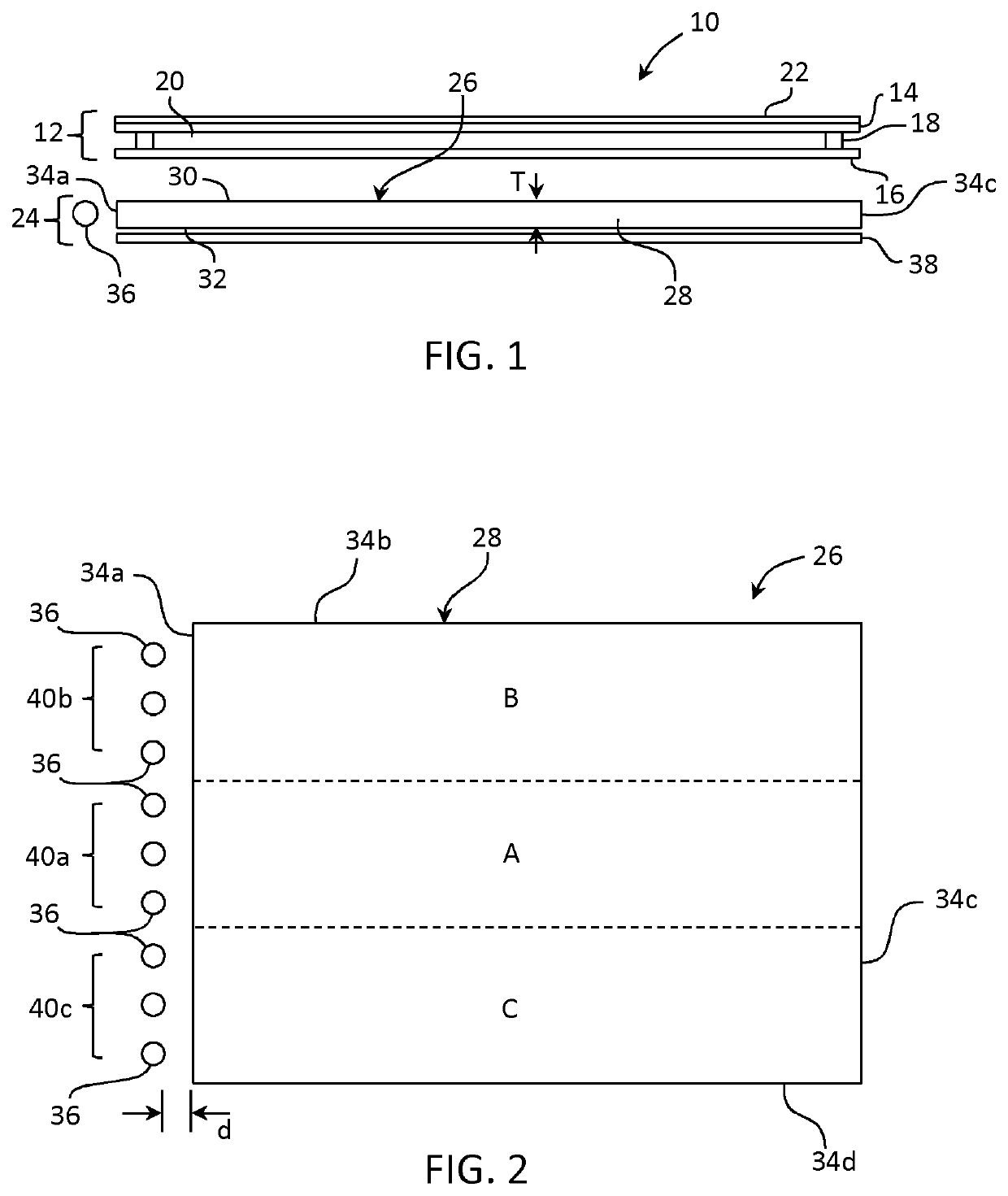
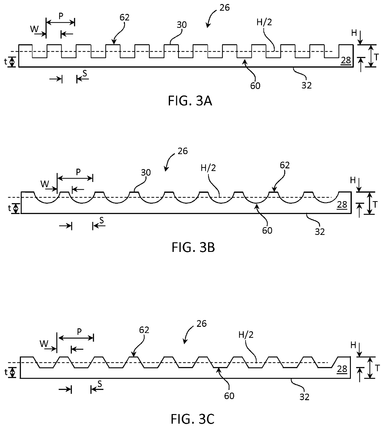
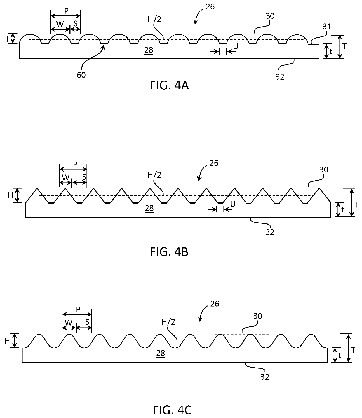
A method of making a glass article, for example a glass light guide plate comprising at least one structured surface including a plurality of channels and peaks. The glass article may be suitable for enabling one dimensional dimming when used in a backlight unit for use as an illuminator for liquid crystal display devices.

Description

CROSS-REFERENCE FOR RELATED APPLICATIONS[0001]This application claims the benefit of priority under 35 U.S.C. § 371 of International Application No. PCT / US18 / 018320, filed on Feb. 15, 2018, which claims the benefit of priority of U.S. Provisional Application Ser. No. 62 / 629,632 filed on Feb. 12, 2018 and U.S. Provisional Application Ser. No. 62 / 459,641 filed on Feb. 16, 2017 and U.S. Provisional Application Ser. No. 62 / 579,525 filed on Oct. 31, 2017 the contents of which are relied upon and incorporated herein by reference in their entirety.BACKGROUNDField[0002]The present disclosure relates generally to a method of making a glass article, for example a glass light guide plate that can be included in a backlight unit for illuminating a liquid crystal display device, and in particular a glass light guide plate including a structured glass surface configured for one dimensional dimming.Technical Background[0003]While organic light emitting diode display devices are gaining in populari...

Claims


Application Information

Patent Timeline
Patent Type & Authority Patents(United States)
IPC IPC(8): C03C19/00C03C3/083C03C15/02F21V8/00
CPCC03C19/00C03C3/083C03C15/02G02B6/0065G02B6/002G02B6/0016G02B6/0078C03C17/3405C03C23/0075G02B6/0038
Inventor CARLETON, TRACIE LYNNEDABICH, II, LEONARD CHARLESDENEKA, DAVID ALANKANUNGO, MANDAKINILI, SHENPINGMI, XIANG-DONGQUESADA, MARK ALEJANDROSENARATNE, WAGEESHASPEECKAERT, JOHN CHARLESSTEMPIN, JR., LOUIS JOSEPHWALCZAK, WANDA JANINAWOLDEGIWORGIS, HAREGEWINE TADESSE
Owner CORNING INC
Learn More