Treatment systems including cover systems and media
- Summary
- Abstract
- Description
- Claims
- Application Information
AI Technical Summary
Benefits of technology
Problems solved by technology
Method used
Image
Examples
first embodiment
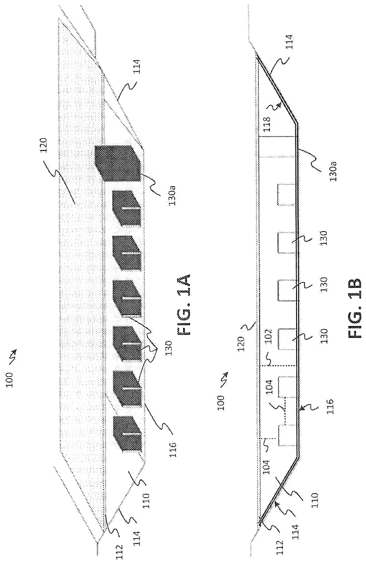
[0029]Referring to FIGS. 1A and 1B, a perspective view and a profile view, respectively, of a treatment system including a storage basin, a cover system, and media is shown as a system 100. As shown in FIGS. 1A and 1B, the system 100 includes a storage basin 110, a cover system 120, and media 130. The storage basin 110 may retain liquid (e.g., wastewater from municipal, industrial, agricultural, or other sources), and the retained liquid may fill the storage basin up to a waterline 112. In an embodiment, one or more perimeter edges 114 of the storage basin 110 may be sloped, as shown in FIGS. 1A and 1B. In an additional or alternative embodiment, the perimeter edges 114 may be vertical, such as when the storage basin is a tank or other manmade structure. In another additional or alternative embodiment, the perimeter edges 114 may include sloped edges and vertical edges.
[0030]The liquid retained in the storage basin 110 may have a depth 102, where the depth 102 corresponds to a dista...
second embodiment
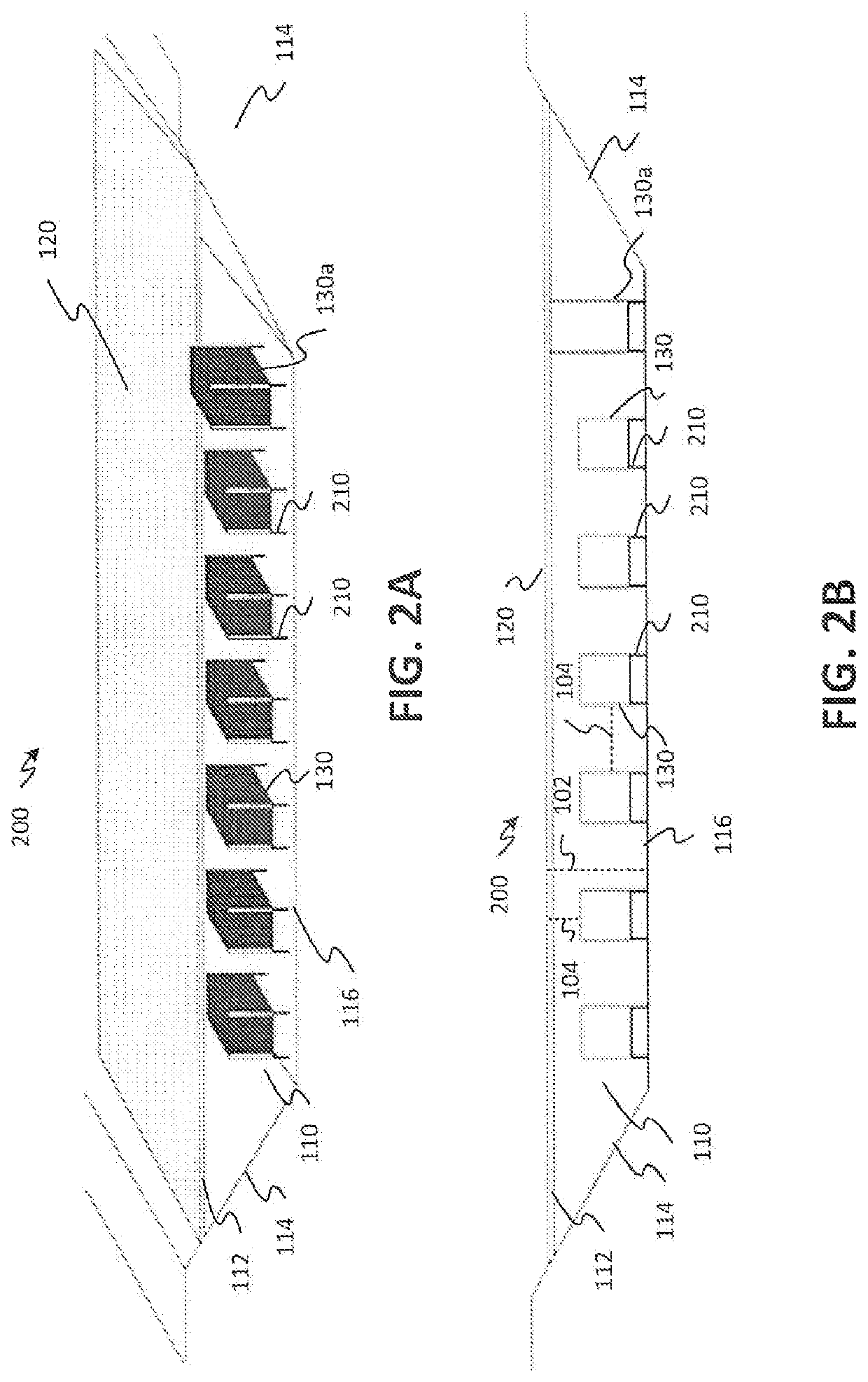
[0049]Referring to FIGS. 2A and 2B, a perspective view, and a profile view, respectively, of a treatment system including a storage basin, a cover system, and media. In FIGS. 2A and 2B, the storage basin 110, the cover system 120 (e.g., a single layer cover system, an insulated cover system, a modular cover system, another form of multi-layer cover system, etc.), and the media 130 of FIGS. 1A and 1B are shown. However, the embodiment of the system 200 illustrated FIGS. 2A and 2B differs from the system 100 of FIGS. 1A and 1B in that the media 130 is situated upon platforms 210. As shown in FIGS. 2A and 2B, the platforms 210 may raise the media off of the floor 116 of the storage basin 110. Thus, in the system 200 of FIGS. 2A and 2B, the media 130 is not in direct contact with a bottom surface (e.g., the floor 116) of the storage basin 110 when the media 130 is supported by the one or more platforms 210. Such a configuration may cause the system 200 to realize improved performance ov...
third embodiment
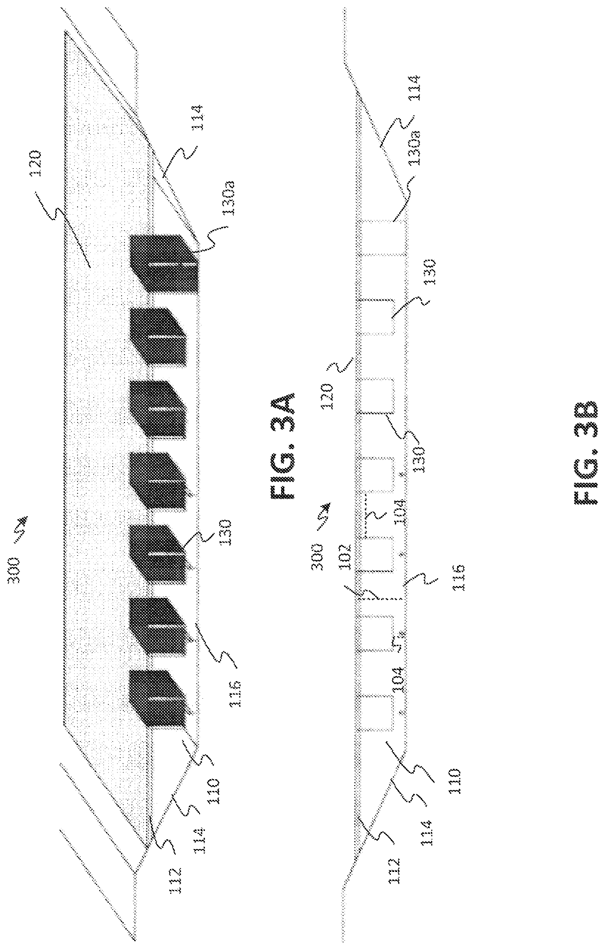
[0052]Referring to FIGS. 3A and 3B, a perspective view, and a profile view, respectively, of a treatment system including a storage basin, a cover system, and media is shown as a system 300. In FIGS. 3A and 3B, the storage basin 110, the cover system 120 (e.g., a single layer cover system, an insulated cover system, a modular cover system, another form of multi-layer cover system, etc.), and the media 130 of FIGS. 1A, 1B, 2A, and 2B are shown. However, the system 300 of FIGS. 3A and 3B differs from the system 100 of FIGS. 1A and 1B and the system 200 of FIGS. 2A and 2B in that the media 130 is coupled to the cover system 120.
[0053]In embodiments utilizing modular cover systems 120, as described above with reference to FIGS. 1A and 1B, the modular cover system may include one or more media modules having media attached thereto. The one or more media modules may be coupled to one or more of the plurality of casings used to form the modular cover system. For example, the media module m...
PUM
 Abstract
Description
Claims
Application Information
 - Generate Ideas
- Intellectual Property
- Life Sciences
- Materials
- Tech Scout
- Unparalleled Data Quality
- Higher Quality Content
- 60% Fewer Hallucinations
Browse by: Latest US Patents, China's latest patents, Technical Efficacy Thesaurus, Application Domain, Technology Topic, Popular Technical Reports.
© 2025 PatSnap. All rights reserved.Legal|Privacy policy|Modern Slavery Act Transparency Statement|Sitemap|About US| Contact US: help@patsnap.com


