Inlet shrouds for fans used principally in water-circulation pumps of swimming pools and spas

a technology for fans and inlet shrouds, which is applied in the direction of machines/engines, mechanical equipment, liquid fuel engines, etc., can solve the problem that the motor fan of the pump will not be useful, and achieve the effect of less clearan

Active Publication Date: 2021-11-23
ZODIAC POOL SYST LLC
View PDF27 Cites 1 Cited by
  • Summary
  • Abstract
  • Description
  • Claims
  • Application Information

AI Technical Summary

Benefits of technology

[0005]The present invention provides a different motor housing design requiring substantially less clearance than do motor housings of pumps similar to that of the Budris patent. In particular, inlets may be included on peripheries of shrouds of the invention (as well as on the rears of the shrouds if desired). Consequently, air need not necessarily be drawn wholly linearly into the shroud, as from the right of the pump in FIG. 1 of the Budris patent. This allows the innovative motor housings to have their shrouds abut, or at least be closely proximate, other objects, without materially diminishing air flow into the shrouds.
[0006]Motor housings of the invention additionally may include vanes or plates within their shrouds. The plates may be positioned so as to reduce, if not eliminate, any significant linear flow of the drawn air through a shroud, instead creating torturous paths through which the air must travel. Channeling air through these torturous paths helps reduce noise as the air moves to the fans. The inventive devices are especially useful as part of pumps of water-circulation systems of swimming pools or spas, although their uses are not limited to these types of objects or systems.
[0011]It is a further optional, non-exclusive object of the present invention to provide motor housings including means within their shrouds for creating torturous paths through which entering air must travel.

Problems solved by technology

If inadequate space is available for air ingestion, the motor fan of the pump will not be useful.

Method used


Image

  • Inlet shrouds for fans used principally in water-circulation pumps of swimming pools and spas
  • Inlet shrouds for fans used principally in water-circulation pumps of swimming pools and spas
  • Inlet shrouds for fans used principally in water-circulation pumps of swimming pools and spas

Examples


Embodiment Construction

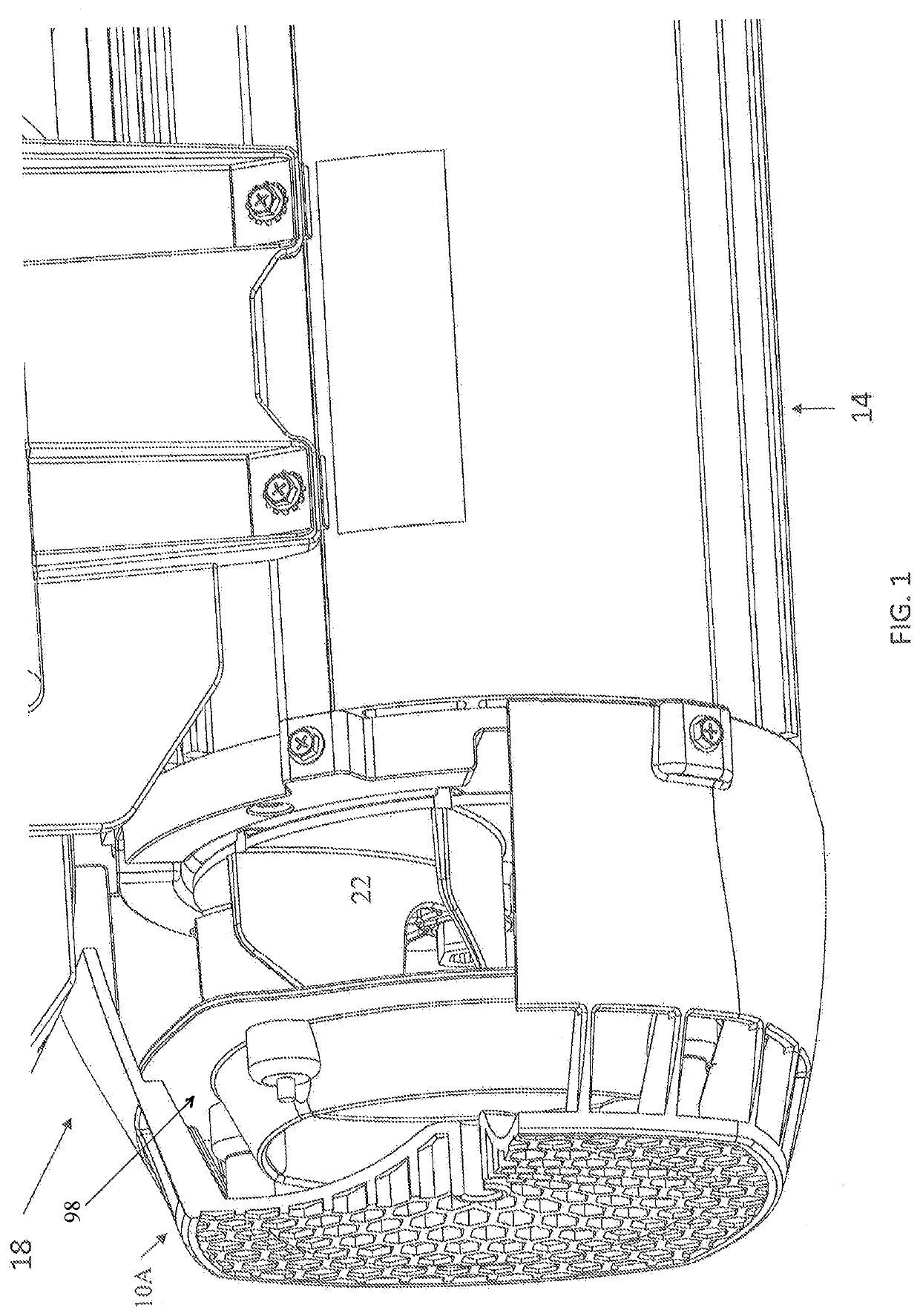
[0019]FIG. 1 illustrates an exemplary shroud 10A forming part of housing 14, which may—but need not necessarily—be connected to or form part of pump 18. Housing 14 contains both a motor and an associated cooling fan 22, with fan 22 preferably positioned within shroud 10. FIG. 1 depicts housing 14 with part of shroud 10A removed so as to show the positioning of fan 22 within the shroud 10A.

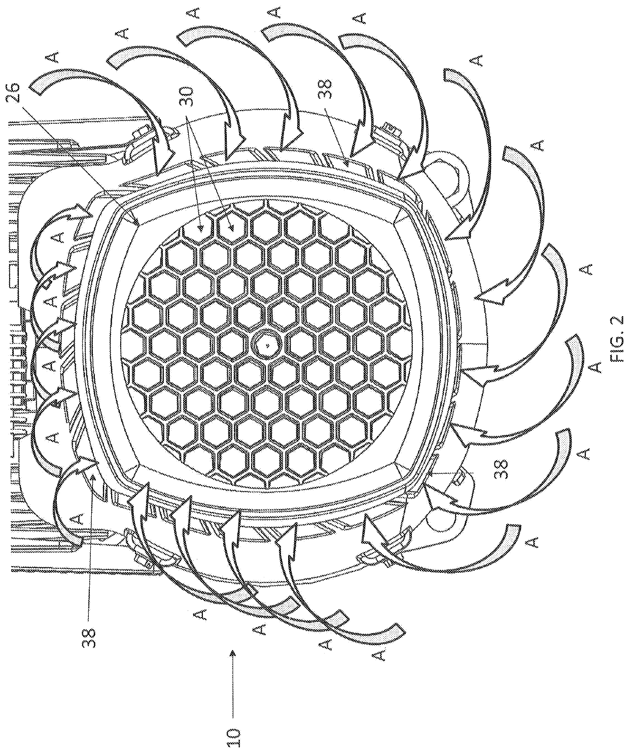
[0020]FIG. 2 provides an elevational, rear view of an alternate shroud 10 and FIG. 6 provides a perspective view of the shroud 10. The shroud 10 includes sides 34 and an end 11, and the end 11 includes a rear surface 26. As is conventional, shroud 10 may—if desired—include open areas in its rear surface 26. Such open areas function as inlets 30 for air drawn into shroud 10 by operation of fan 22. However, in the present invention inlets 30 are not necessary for satisfactory function of pump 18. This is because sides 34 of shroud 10 (see FIG. 6) also include openings forming inlets 38 for air drawn ...


PUM


Abstract

Motor housings and shrouds are detailed. Inlets of the shrouds may be included on any or all portions of their peripheries (as well as on rears of shrouds if desired). Air hence need not necessarily be drawn wholly linearly into the shrouds, permitting the shrouds to abut, or at least be closely proximate, other objects without materially diminishing air flow into the shrouds. Moreover, plates within the shrouds may be positioned so as to create torturous paths through which the air must travel. Channeling air through these torturous paths helps reduce noise as the air moves to the fans.

Description

CROSS-REFERENCE TO RELATED APPLICATION[0001]This application claims the benefit of and priority to U.S. Provisional Patent Application Ser. No. 62 / 599,049, filed Dec. 15, 2017, and having the same title as appears above (the “Provisional Application”), the entire contents of which Provisional Application are hereby incorporated herein by this reference.FIELD OF THE INVENTION[0002]This invention relates to air inlets for motor-containing devices (such as, but not limited to, housings connected to pumps) and more particularly, although not necessarily exclusively, to shrouds through which air may be drawn by cooling fans associated with the motors.BACKGROUND OF THE INVENTION[0003]U.S. Pat. No. 5,156,535 to Budris, et al., whose contents are incorporated herein by this reference, describes a pump for a spa. The pump includes both a motor and a fan designed “to draw ambient air into the motor housing, through the stator laminations, over the field coils, armature, commutator and brushes...

Claims


Application Information

Patent Timeline
Patent Type & Authority Patents(United States)
IPC IPC(8): F04D25/08F04D29/14F04D29/58F04D29/44H02K5/20H02K9/06F04D13/06F04D29/42
CPCF04D25/082F04D13/06F04D29/4226F04D29/4293F04D29/441F04D29/5806F04D29/588H02K5/20H02K9/06H02K5/207
Inventor HOHN, JAMESBORG, DUSTIN
Owner ZODIAC POOL SYST LLC
Why Eureka
Try Eureka