Domestic appliance with door opener

a technology of domestic appliances and door openers, applied in the field of domestic appliances, can solve the problems of inability to be reached and the door to be pushed open, and achieve the effects of facilitating adaptation, imparting flexibility, and inherent elasticity

Active Publication Date: 2021-11-23
EMZ HANAUER
View PDF12 Cites 0 Cited by
  • Summary
  • Abstract
  • Description
  • Claims
  • Application Information

AI Technical Summary

Benefits of technology

[0006]In the solution according to the invention, the flexible form of the push slider in at least a section thereof permits a curved movement of the push slider when it is moved out of its retracted position into the deployed position. On installation of the door-opening mechanism, the possibility of a curved movement of the push slider provided by the flexible section facilitates adaptation to the available, possibly confined space conditions within that of the two main components of the domestic appliance on which the door-opening mechanism is to be arranged. For example, in the case of a washing machine, the door-opening mechanism can be accommodated in the body of the washing machine despite the presence of bulky concrete weights, without having to accept limitations as regards the stroke length between the retracted position and the deployed position of the push slider.
[0007]The flexibility of the section of the push slider can be due to elastic bendability or / and to articulation. For example, the push slider can have one or more portions which are manufactured from an elastic material and are therefore elastically deformable. Alternatively or in addition, the push slider can have a plurality of elements which are articulated with one another and impart flexibility to the push slider as a whole on account of the articulated connection. The elements as such can be rigid or possess inherent elasticity.
[0020]In other embodiments, the push slider is a component that is separate from the door-closing mechanism and does not take part in the closing function of the door-closing mechanism. In the case of the second aspect of the invention, the push slider can then act in a pressure-exerting manner on the body or on a component arranged on the body as it moves out of the retracted position into the deployed position, whereby it overcomes a holding-closed action of the door-closing mechanism and opens the closed door. The push slider can, for example, push against a fixed contact surface arranged on the body, for example against the outside of a wall portion of a body housing extending all round the access opening. Alternatively, the push slider can cooperate with a movable component arranged on the body, which movable component can grip and hold the push slider as the door closes. Such a configuration can be used not only to open the door by sliding the push slider forwards, but subsequently to close the door again by retraction of the push slider. In some embodiments, a gripping element that is mechanically and physically separate from the door-closing mechanism is therefore arranged on the body, which gripping element, when the door is closed and when the push slider is moved forwards out of the retracted position into the deployed position, maintains a gripping engagement with the push slider so that the maintained gripping engagement has the effect that the door closes again when the push slider is subsequently retracted.
[0024]In some embodiments of the first or / and second aspect of the invention, a slip clutch is arranged in the force transmission path between a driving force generator of the drive unit and the push slider. The slip clutch can prevent damage to the driving force generator (e.g. drive motor) if, despite activation of the door-opening mechanism, the door cannot be opened, for example because a user is inadvertently pushing against the door or because there is a heavy weight in front of the door.

Problems solved by technology

In some domestic appliances, the available installation space may be insufficient to accommodate therein a pusher which is movable linearly between a retracted position and a deployed position and, when moved into its deployed position, causes the door to be pushed open.
For the desired partial opening of the door, a movement stroke of the pusher of several centimetres may be required, which may not be available in some domestic appliances owing to the structural conditions.

Method used


Image

  • Domestic appliance with door opener
  • Domestic appliance with door opener
  • Domestic appliance with door opener

Examples


Embodiment Construction

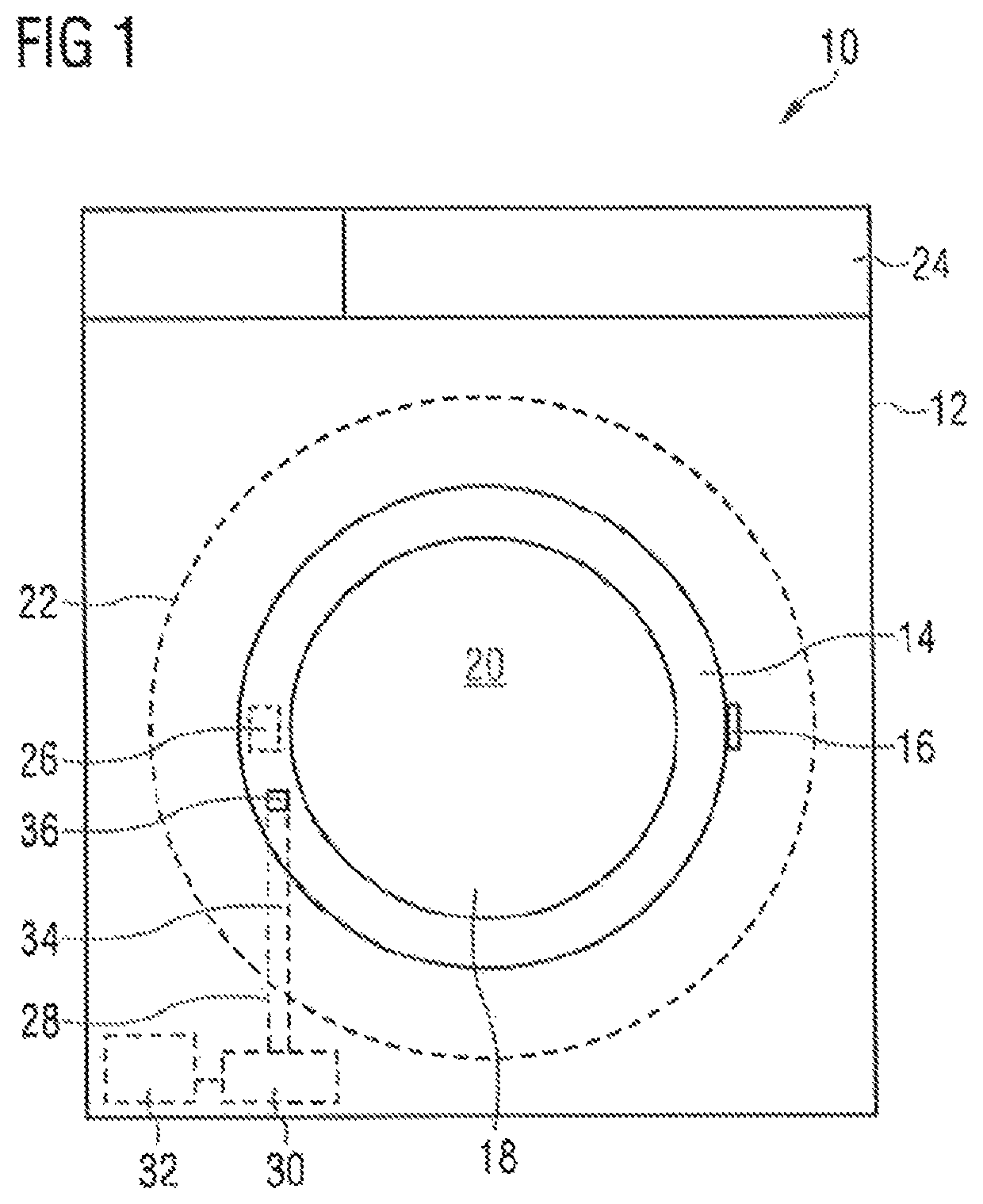
[0035]The preferred embodiments of the present invention are illustrated in FIGS. 1-13. Reference will first be made to FIG. 1. The domestic washing machine shown therein is designated generally 10. It is representative of the large number of different types of domestic appliances which can be equipped with a door-opening mechanism according to the invention. The washing machine 10 has a body 12 to which a door 14 is pivotably attached. A pivot hinge is shown schematically at 16, by means of which hinge the door 14 is mounted on the body 12. A bull eye 18 (as is conventional in washing machines of the front loader type) in the door 14 allows the user to see into the washing chamber (process chamber) designated 20, in which the laundry to be cleaned is situated. The washing chamber 20 is formed in a washing drum 22, indicated by means of a broken line, which is rotatably mounted in a suds container, not shown in greater detail.

[0036]On the front side of the washing machine 10 facing ...


PUM


Abstract

A domestic appliance, for example a washing machine, comprises a body having an access opening to a process chamber arranged inside the body, a door which is movably attached to the body and which closes the access opening in a closed position, a door-closing mechanism for holding the door closed in its closed position and a door-opening mechanism arranged on the body or on the door, having a push slider, which is movable between a retracted position and a deployed position, and a drive unit for driving the push slider. A transfer of the push slider out of the retracted position into the deployed position effects opening of the closed door, the push slider acts in a pressure-exerting manner on the door or on the body and thereby overcomes a holding-closed action of the door-closing mechanism and opens the closed door.

Description

BACKGROUND OF THE INVENTION1. Field of the Invention[0001]The present invention relates generally to a domestic appliance having a door-opening function2. Description of the Prior Art[0002]The usual equipment of modern households includes a wide variety of appliances which have a process chamber arranged inside an appliance body, as well as a door by means of which an access opening to the process chamber can be closed. In the process chamber, objects can be subjected to a treatment process, for example cleaning or cooking. Examples of such appliances are accordingly a washing machine, a tumble dryer, a dishwasher, an oven and the like. In particular in the case of those domestic appliances in which there is a comparatively large amount of moisture in the process chamber at the end of a program run, either in the form of hot steam, for example, in the case of a dishwasher or in the form of wet laundry in the case of a washing machine, it is sometimes desirable to be able to partiall...

Claims


Application Information

Patent Timeline
Patent Type & Authority Patents(United States)
IPC IPC(8): E05F15/627A47L15/42E05F3/00E05F15/619D06F39/14D06F58/20
CPCA47L15/4259A47L15/4261A47L15/4263D06F39/14D06F58/20E05F3/00E05F15/619E05F15/627E05Y2201/604E05Y2900/304E05Y2900/312D06F37/28E05Y2201/426E05Y2201/656
Inventor SPIESSL, GEORGDIRNBERGER, ALBERTSCHEMELA, BENJAMIN
Owner EMZ HANAUER
Why Eureka
Try Eureka