
Hoodie cap visor

a visor and hoodie technology, applied in the field of headwear, can solve the problems of increasing the risk of cataracts in humans, violent altercations, and increasing the risk of cataracts, and achieve the effect of providing additional privacy for the wearer, quick, easy, and selectively

Active Publication Date: 2021-11-23
INTRO TECH AUTOMOTIVE
View PDF38 Cites 1 Cited by
  • Summary
  • Abstract
  • Description
  • Claims
  • Application Information

AI Technical Summary

Benefits of technology

[0012]The present invention is of bill cap that not only provides an ability to quickly, easily, and selectively provide additional shading for the wearer, but also provides additional privacy for the wearer such as when the wearer is a celebrity who does not want to be noticed in public such as by paparazzi.
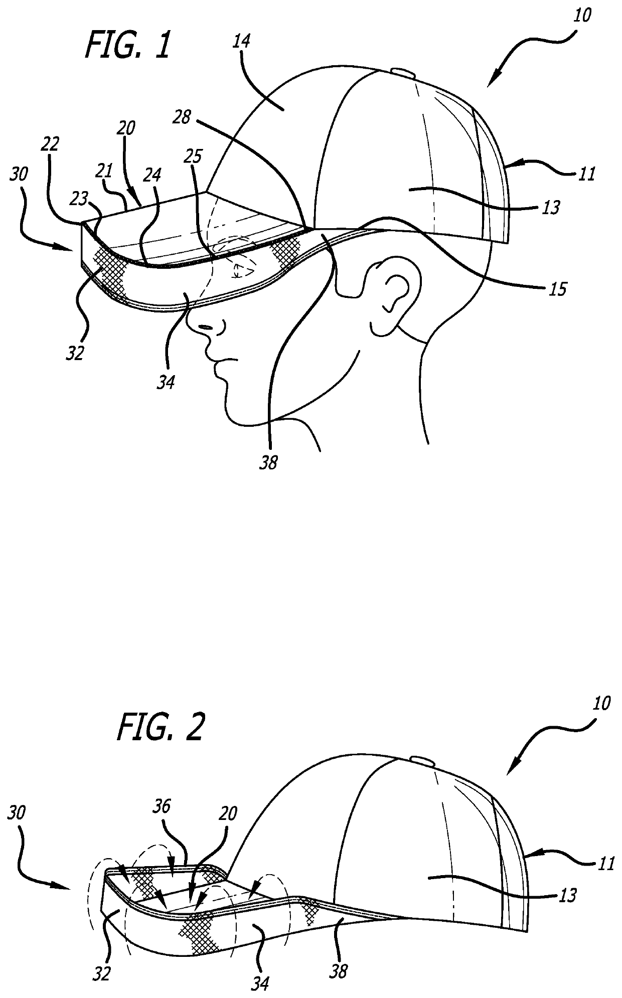
[0013]The present invention is of a cap such as of a bill cap or baseball cap having a bill and an elastic panel that depends downwardly from the periphery of the bill. The downwardly depending panel provides additional privacy and protection from the sun. However because the panel is made of or contains an elastic material, it can be quickly and easily flipped between its downward position and an upward position in which the cap functions as a traditional bill cap.
[0014]When flipped down, or in the downward position, the elastic panel lies provides more shading and privacy than a standard bill cap. In this position a wearer can raise or lower his head so that he can see straight forward or at least sufficiently far in front of him to allow him to walk, ride a bicycle, etc. safely, while the side portions of the panel at least partially obscure his eyes as seen from the side, thus providing both shading for his eyes as well as privacy such as from paparazzi.
[0015]When flipped up, or in the upward position, the elastic band is no longer within the user's line of sight and thus provides greater visibility, both for the wearer looking outward and for other people looking inward at the wearer's face. The cap might be worn, for example, by an outdoorsman who wants to be able to flip the panel downward to provide maximum shading and protection from the sun, and then flip the panel back into its original configuration when the shading provided by a regular bill cap will suffice. The cap might also be worn, for example, by a celebrity who nominally wants the shading provided by a regular baseball cap, but also wants to be able to quickly flip the panel downward for extra privacy so that she is less recognizable on the street.
[0016]In this way the elastic panel functions as a positionable hood for the cap. The overall function of the cap is similar to that of a “hoodie” jacket, in that the wearer can quickly and easily pull the panel down for greater privacy / reduced recognizability. The inventor has thus coined the name “hoodie cap visor” for this invention.
[0018]In one aspect therefore, the invention is of a bill cap for providing shade and for selectively providing additional shade and privacy to a wearer. The bill cap includes a crown adapted to be placed over a top of the wearer's head, the crown having at least a front portion, a left side portion, and a right side portion. The bill cap further includes a bill that extends generally forward from the crown front portion, extending far enough forward to provide shading from the sun for eyes of the wearer, and an elastic panel attached to the bill's front, left side, and right side edges. The panel can be elastic either by way of its being all elastic, or by way of its having one or more elastic chords or bands captured within the band, sewn to it, or otherwise affixed to it. The elastic panel may be flipped between a first and upper position and a second and lower position. In its upper position, the panel extends generally upwardly from the edges of the bill, and the bill cap functions much like a traditional bill cap. It its lower position, the panel extends generally downwardly from the edges of the bill, thus providing additional shading to the eyes of the wearer against sunlight, and also additional privacy that makes it more difficult for others to recognize the wearer, especially from the side.

Problems solved by technology

Chronic exposure to sunlight has been demonstrated to increase the risk of cataracts in humans.
Additionally, interpersonal friction between celebrities who do not want to be photographed, pursued, or otherwise hounded by paparazzi, and the paparazzi themselves, has increased dramatically in recent years, even leading to violent altercations in some instances.

Method used


Image

  • Hoodie cap visor
  • Hoodie cap visor
  • Hoodie cap visor

Examples


first embodiment

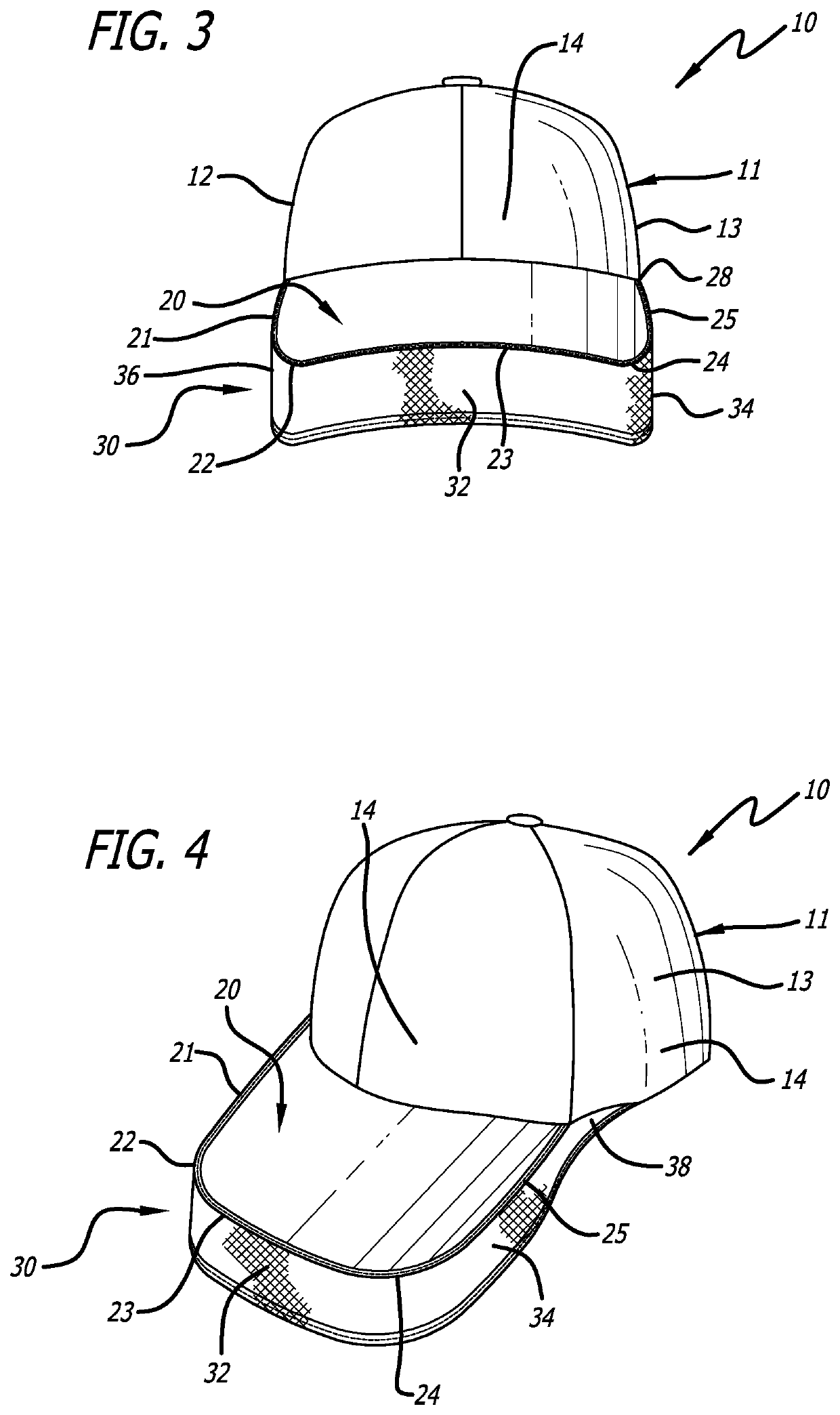
[0032]FIG. 1 is a top left perspective view of a person wearing the bill cap 10 according to the present invention, with the elastic panel 30 flipped into its downward position for greater shade and privacy. Bill cap 10 includes a crown 11 which is adapted to fit over a top of a head of a wearer. Crown 11 includes a right side portion 12 (FIG. 3), a left side portion 13, and a front portion 14. A bill 20 is attached to, and extends generally forward from, the crown front portion 14. Bill 20 provides shading against sunlight for the wearer's eyes. The structure described in this paragraph is conventional so far.

[0033]Unconventionally, bill cap 10 also has an elastic panel 30 attached to the bill at the bill's right edge 21, curved right front corner 22, front edge 23, curved left front corner 24, and left edge 25, and in this embodiment elastic panel 30 extends past the bill's rearmost portion 28. The term “elastic” as used herein and in the claims appended hereto is used in its broa...

second embodiment

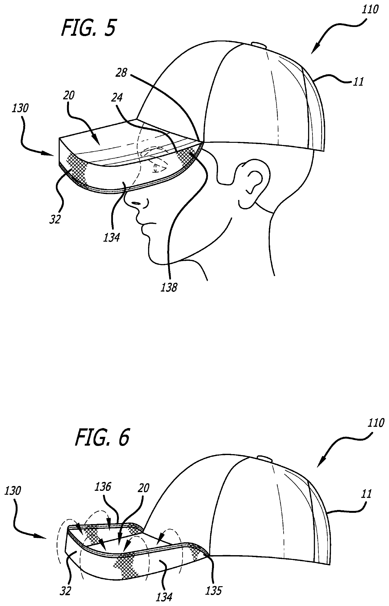
[0040]FIG. 5 is a top left perspective view of a user wearing a bill cap 110 according to the present invention, with the elastic panel 130 flipped into its downward position for greater shade and privacy. In this embodiment the side portions 134, 136 of elastic panel 130 do not extend rearwardly past a rearmost extent of bill 20. That is, rearmost portion 138 of panel 130 extends only to the rearmost extent 28 of bill 20 and no further. Otherwise this embodiment functions similarly to the embodiment of FIG. 1.

[0041]FIG. 6 is a top left perspective view of the bill cap 110 of FIG. 5 with the elastic panel 130 flipped into its upward position for less shade and privacy. As can be seen, the flipping between the upward position and downward position is completed by rotating the elastic panel 130 about the bill 20.

[0042]FIG. 7 is a front elevation view of the bill cap 110 of FIG. 5 without the wearer, and FIG. 8 is a top left perspective view thereof.

[0043]Elastic panel 30 can be of a u...

third embodiment

[0044]FIG. 9 is a top left perspective view of user wearing a bill cap 210 according to the present invention, with the elastic panel 230 flipped into its downward position for greater shade and privacy. In this embodiment elastic panel 230 is of non-uniform width. More specifically, elastic panel 230 is narrower at its front portion 232 than it is at its left and right side portions 234, 236. In this embodiment when the wearer flips down elastic panel 230, his forward vision is not obscured as much as with the prior embodiments. Thus, the wearer does not need to tilt his head as far back in order to still see forward for safety or other reasons, while still keeping his eyes obscured or at least partially obscured from the side. More generally, elastic panel 230 could even comprise two separate panels that extend from the side edges of bill 20 and at least partially onto the front and left side corner edges 22, 24 of the bill so that they can be elastically flipped, but without any ...


PUM


Abstract

A bill cap or baseball cap has a crown and a bill as conventional. Additional, the bill cap has an elastic panel affixed at an edge thereof to front and left side edges of the bill. The elastic panel is capable of being flipped between an upward position in which the panel extends upwardly from the bill, and a downward position in which the panel extends downwardly from the bill. In the downward position the panel provides additional shading for the eyes of the wearer and / or privacy for the wearer when viewed from the side, thus providing additional anonymity for the wearer such as from paparazzi.

Description

CROSS-REFERENCE TO RELATED APPLICATIONS[0001]None.BACKGROUND OF THE INVENTION1. Field of the Invention[0002]This invention relates to the field of headware. More particularly, this invention relates to the field of a visor having a flippable hoodie portion that selectably provides increased privacy and sun protection.2. Description of Related Art[0003]It is vital to the health of the human eye to shield and protect the eye from sunlight, and particularly from the sun's ultraviolet (UV) rays. Chronic exposure to sunlight has been demonstrated to increase the risk of cataracts in humans. See, e.g., National Eye Institute, “New research sheds light on how UV rays may contribute to cataract,” Jun. 3, 2014.[0004]Caps and hats for shielding the wearer's eyes from direct sunlight are ubiquitous. Bill caps, sometimes referred to as baseball caps or visor caps, are common. Bill caps have a crown portion that fits over the head of the wearer and a bill attached to the front of the crown. The ...

Claims


Application Information

Patent Timeline
Patent Type & Authority Patents(United States)
IPC IPC(8): A42B1/0182A42B1/0184
CPCA42B1/0182A42B1/0184A42B1/0185
Inventor LENTERMAN, HENRI
Owner INTRO TECH AUTOMOTIVE
Learn More