Curved eye protection shield for welding protection

a welding protection and shield technology, applied in eye surgery, eye masks, engineering safety devices, etc., can solve the problem of non-uniform thickness of the protective cover formed by the inner and outer surface, and achieve the effect of maximizing the darkening

Active Publication Date: 2021-09-28
3M INNOVATIVE PROPERTIES CO
View PDF56 Cites 0 Cited by
  • Summary
  • Abstract
  • Description
  • Claims
  • Application Information

AI Technical Summary

Benefits of technology

[0008]The invention is advantageous in that it provides for a curved eye protection shield having no or a minimized refractive power. Further, the invention allows for compensating a refractive power of a curved darkening filter. The invention further provides for a maximized convenience for a wearer of a welding protector having a curved darkening filter, in providing an eye protector with minimized refractive power.
[0022]In a further embodiment the darkening filter comprises liquid crystals arranged in direct contact between a first and second alignment layer, the first and second alignment layer being arranged on a first and a second transparent electrode layer, respectively, and the first and second transparent electrode layer are arranged on a first and a second transparent layer, respectively, and wherein the first and a second transparent layer are each provided with a polarizer. The first and second transparent layer, first and second electrode layer and first and second alignment layer form a liquid crystal cell. In a preferred embodiment the eye protection shield comprises two liquid crystal cells arranged in optical sequence. This means that a light beam impinging on perpendicular on the eye protection shield passes both liquid crystal cells at least in the light-transmission-state. In such an embodiment one polarizer may be arranged between the two liquid crystal cells and the so formed sandwich of the two liquid crystal cells may be arranged between further two polarizers. Accordingly, such an embodiment has three polarizers and two liquid crystal cells. This is advantageous to provide a maximized darkening effect in the dark-state and a sufficient light transmission state in the light-transmission-state.

Problems solved by technology

Further, because the inner and outer surface of the protective cover being non-equidistant the portion of the protective cover formed by the inner and outer surface has a non-uniform thickness (defined between the inner and outer surface of the protective cover).

Method used


Image

  • Curved eye protection shield for welding protection

Examples


Embodiment Construction

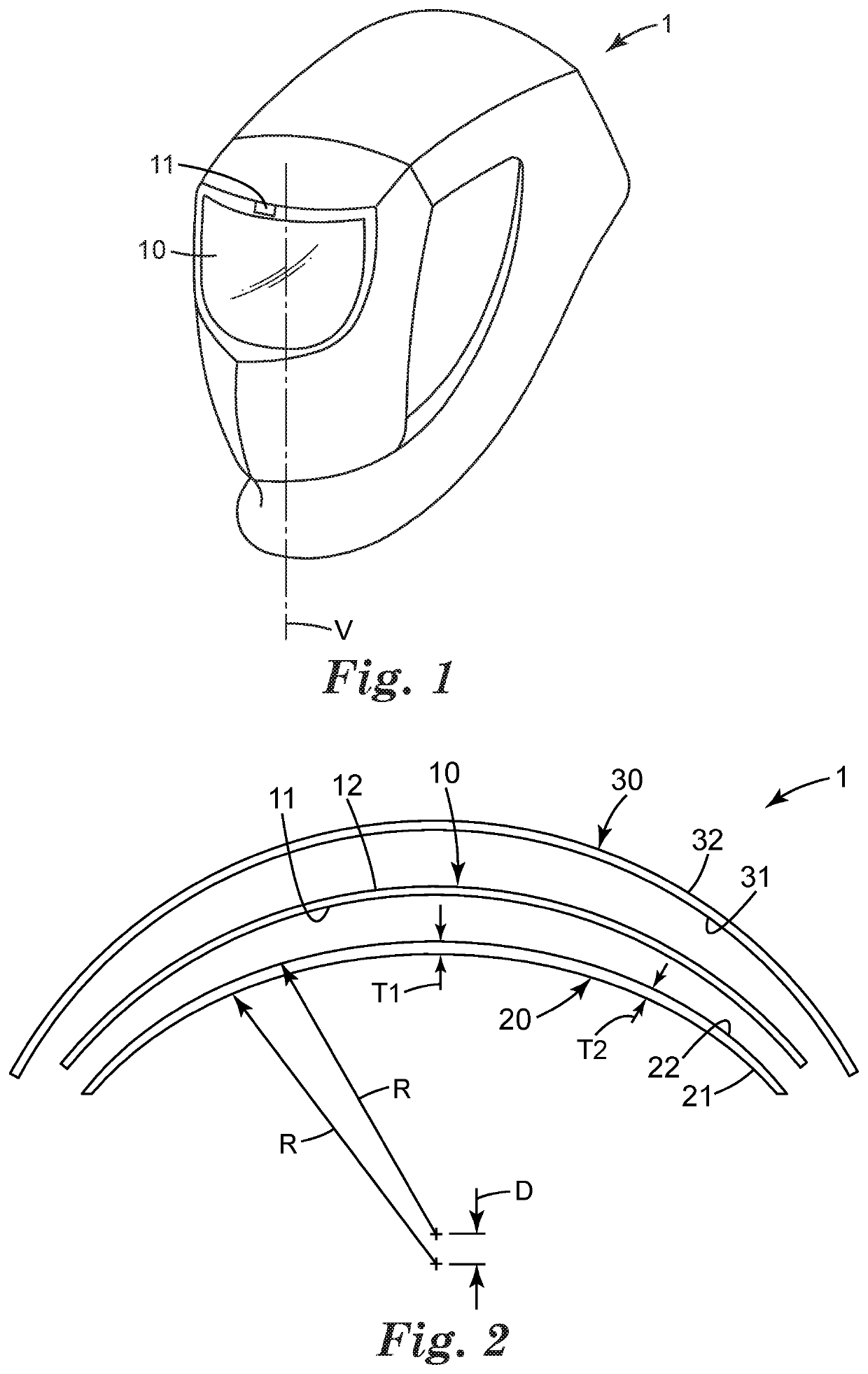
[0035]FIG. 1 shows a curved eye protection shield 1 for welding protection. The eye protection shield 1 has an electrically switchable darkening filter 10, an inner protective cover 20 and an outer protective cover 30.

[0036]The darkening filter 10 is an automatic darkening filter, in the example is based on a liquid crystal cell. The darkening filter 10 is electrically switchable between a light-transmission-state and a dark-state. When switched in the dark-state, the darkening filter 10 blocks a significant amount of light from being transmitted therethrough. This enables a user to observe a welding arc by seeing through the darkening filter 10 without risking to be exposed to harmful light radiation from the welding arc. In the light-transmission-state the darkening filter 10 permits a significant amount of light to be transmitted therethrough. Thus, the darkening filter 10 in the light-transmission-state allows the user to see under ambient light conditions (in the absence of the...


PUM


Abstract

A curved eye protection shield for welding protection. The eye protection shield has an electrically switchable darkening filter and a protective cover. The darkening filter has eye facing major inner and outer surfaces, and the protective cover has major inner and outer surfaces. The protective cover is provided for arrangement on the inner surface of the darkening filter. The inner and outer surface of the darkening filter are equidistant, whereas the inner and outer surface of the protective cover are non-equidistant. The invention is advantageous in that it provides an eye protection shield having a minimized refractive power.

Description

CROSS REFERENCE TO RELATED APPLICATIONS[0001]This application is a national stage filing under 35 U.S.C. 371 of PCT / US2017 / 030344, filed May 1, 2017, which claims the benefit of European Application No. 16168229.9, filed May 4, 2016, the disclosure of which is incorporated by reference in its / their entirety herein.FIELD OF THE INVENTION[0002]The invention relates to a curved eye protection shield for welding protection, and in particular to a curved eye protection shield which comprises an electrically switchable darkening filter having two equidistant major surfaces, and a protective cover having two non-equidistant major surfaces.BACKGROUND ART[0003]Automatic darkening filters commonly have a switchable filter that automatically changes from a light-transmission-state to a dark-transmission-state in response to incident light. The switching is generally achieved through use of a photodetector that is located on, or as part of, personal protective equipment. The photodetector recog...

Claims


Application Information

Patent Timeline
Patent Type & Authority Patents(United States)
IPC IPC(8): A61F9/06
CPCA61F9/061A61F9/06A61F9/067A61F9/065F16P1/06
Inventor MAGNUSSON, KRISTINA M.JAREFORS, KENNETHFROISSARD, LAURENTBILLINGSLEY, BRITTON G.
Owner 3M INNOVATIVE PROPERTIES CO
Why Eureka
Try Eureka