
Method and control system for control of dosage of a reducing agent

a technology of reducing agent and control system, which is applied in the direction of machines/engines, engine components, mechanical apparatus, etc., can solve the problems of unreliable control of the amount of reducing agent to be injected, no/sub>x/sub>become unnecessary high, and achieve the effect of robust control

Active Publication Date: 2021-09-21
SCANIA CV AB
View PDF13 Cites 0 Cited by
  • Summary
  • Abstract
  • Description
  • Claims
  • Application Information

AI Technical Summary

Benefits of technology

[0011]When the closed loop control is based on inaccurate NOx values, the control of the injection of the reducing agent may also result in excessive injection of reducing agent into the exhaust stream. If too much reducing agent is injected into the exhaust stream, there is a risk that residues / precipitates / crystallizations (hereafter commonly denoted residues and / or deposits) of additive / reducing agent are formed downstream of the dosage device injecting the additive / reducing agent into the exhaust stream e.g. in an evaporation chamber. Such reducing agent residues of reducing agent being formed in the exhaust treatment system potentially increase the back pressure in the exhaust treatment system, and therefore potentially also increase the fuel consumption for the engine. Also, such additive / reducing agent residues in the exhaust treatment system may have a negative effect on the general purification performance of the exhaust treatment system, since the additive / reducing agent residues in the evaporation chamber reduces the evaporation efficiency, which may result in that too little evaporated reducing agent reaches the SCR catalyst.
[0092]a robustness of the control of the dosage of the reducing agent.

Problems solved by technology

However, in known solutions, the control of the amount of reducing agent to be injected is not very exact / reliable, since the nitrogen oxides NOx sensor does not provide an accurate value and / or has a sensor error.
Essentially, if too little reducing agent is injected due to the inaccurate / non-optimized closed loop control, the emission of nitrogen oxides NOx becomes unnecessary high, and might even be deficient / unacceptable such that it exceeds allowed emission standard values / requirements for nitrogen oxides NOx.
However, the engine runs more fuel efficient if it is allowed to produce more nitrogen oxides NOx, wherefore such an engine control may result in unnecessarily increased fuel consumption.
When the closed loop control is based on inaccurate NOx values, the control of the injection of the reducing agent may also result in excessive injection of reducing agent into the exhaust stream.
If too much reducing agent is injected into the exhaust stream, there is a risk that residues / precipitates / crystallizations (hereafter commonly denoted residues and / or deposits) of additive / reducing agent are formed downstream of the dosage device injecting the additive / reducing agent into the exhaust stream e.g. in an evaporation chamber.
Such reducing agent residues of reducing agent being formed in the exhaust treatment system potentially increase the back pressure in the exhaust treatment system, and therefore potentially also increase the fuel consumption for the engine.
Also, such additive / reducing agent residues in the exhaust treatment system may have a negative effect on the general purification performance of the exhaust treatment system, since the additive / reducing agent residues in the evaporation chamber reduces the evaporation efficiency, which may result in that too little evaporated reducing agent reaches the SCR catalyst.
The increased back pressure and / or the less efficient exhaust purification of the exhaust treatment system may also result in a number of control system related problems.

Method used


Image

  • Method and control system for control of dosage of a reducing agent
  • Method and control system for control of dosage of a reducing agent
  • Method and control system for control of dosage of a reducing agent

Examples


Embodiment Construction

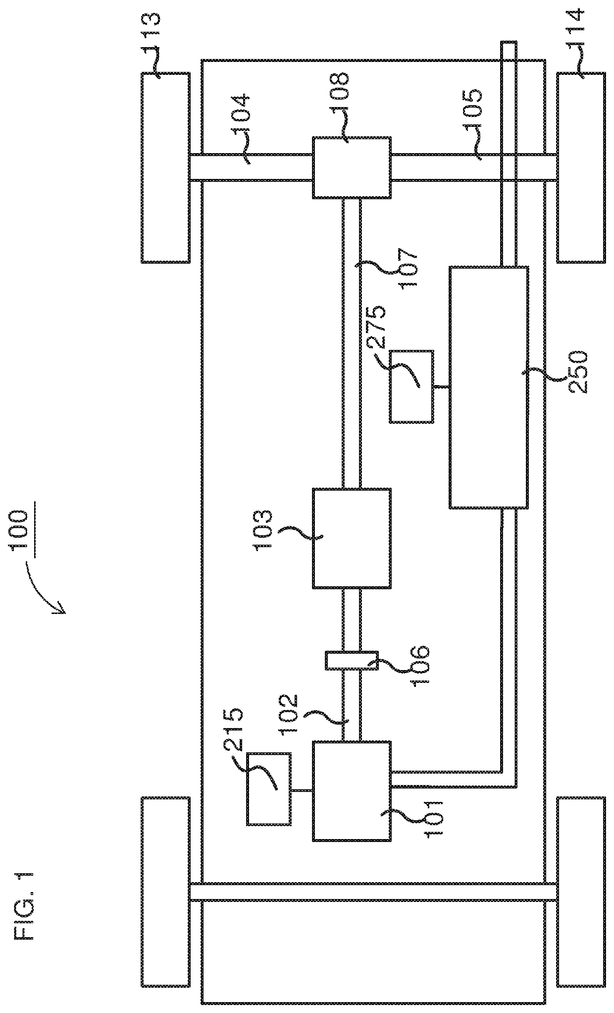
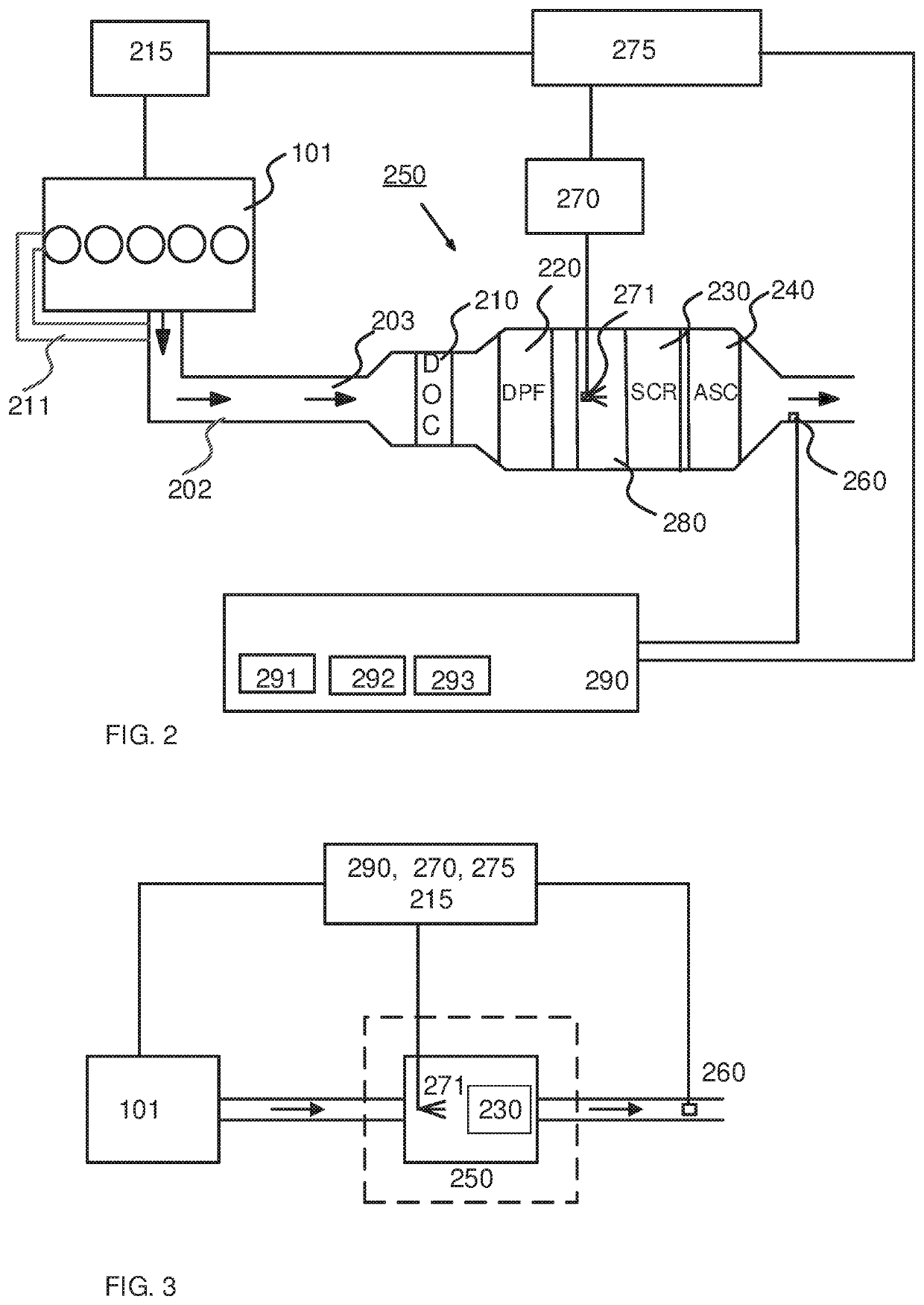
"d_n">[0102]FIG. 1 schematically shows an example vehicle 100 comprising an exhaust treatment system 250. The powertrain comprises a combustion engine 101, which in a customary manner, via an output shaft 102 on the combustion engine 101, usually via a flywheel, is connected to a gearbox 103 via a clutch 106.

[0103]The combustion engine 101 is controlled by the engine's control system via a control device 215. Likewise, the clutch 106 and the gearbox 103 may be controlled by the vehicle's control system, with the help of one or more applicable control devices (not shown). Naturally, the vehicle's powertrain may also be of another type, such as a type with a conventional automatic gearbox, of a type with a hybrid powertrain, etc. A Hybrid powertrain may include the combustion engine and at least one electrical motor, such that the power / torque provided to the clutch / gearbox may be provided by the combustion engine and / or the electric motor.

[0104]An output shaft 107 from the gearbox 10...


PUM


Abstract

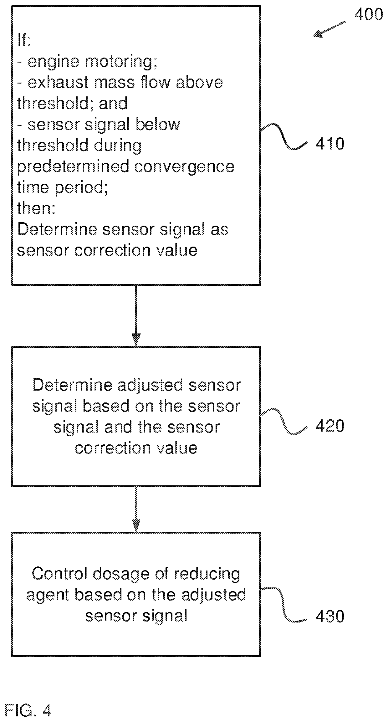
Disclosed is a method for control of dosage of a reducing agent into an exhaust stream, which includes: determining at least one sensor signal SNOx from at least one nitrogen oxides NOx sensor arranged downstream of at least one of the one or more reduction catalysts as at least one sensor correction value SNOx_corr, respectively, if: 1) the engine rotates without fuel supply; 2) an exhaust mass flow M′exh is greater than an exhaust mass flow threshold M′exh_th; M′exh>M′exh_th; and 3) the sensor signal SNOx has had a value smaller than a sensor signal threshold SNOx_th; SNOx<SNOx_th; during at least a predetermined time period Tcon; determining at least one adjusted sensor signal SNOx_adj based on the at least one sensor signal SNOx and the at least one sensor correction value SNOx_corr, respectively; and controlling the dosage of the reducing agent based on the at least one adjusted sensor signal SNOx_adj.

Description

CROSS-REFERENCE TO RELATED APPLICATIONS[0001]This application is a National Stage Application (filed under 35 § U.S.C. 371) of PCT / SE2019 / 050364, filed Apr. 18, 2019 of the same title, which, in turn claims priority to Swedish Application No. 1850482-9 filed Apr. 24, 2018 of the same title; the contents of each of which are hereby incorporated by reference.FIELD OF THE INVENTION[0002]The present invention relates to a method control of dosage of a reducing agent into an exhaust stream, according to the preamble of claim 1. The present invention also relates to a system arranged for control of dosage of a reducing agent into an exhaust stream, according to the preamble of claim 15. The invention also relates to a computer program and a computer-readable medium, which implement the method according to the invention.BACKGROUND OF THE INVENTION[0003]The following background description constitutes a description of the background to the present invention, and thus need not necessarily co...

Claims


Application Information

Patent Timeline
Patent Type & Authority Patents(United States)
IPC IPC(8): F01N3/20F01N11/00F01N9/00
CPCF01N3/206F01N9/00F01N11/00F01N2560/026F01N2610/02F01N3/2066F01N2610/146F01N2900/1402F01N2900/08F01N2900/0408F01N2900/1411F01N2430/02Y02A50/20Y02T10/12F01N3/208F01N2560/021F01N2390/02F01N2550/05F01N2610/144F01N2900/0416
Inventor LUNDBERG, CHRISTER
Owner SCANIA CV AB
Learn More