
Indium phosphide based optical transmitter with single parameter driven phase correction for temporal variation

a technology of optical transmitter and phase correction, applied in non-linear optics, instruments, optics, etc., can solve the problems of high-fidelity transfer of rf signal into modulation of optical signal, interfering optical signals, etc., and achieve the effect of significant simplified system

Active Publication Date: 2021-09-14
NEOPHOTONICS CORP
View PDF18 Cites 3 Cited by
  • Summary
  • Abstract
  • Description
  • Claims
  • Application Information

AI Technical Summary

Benefits of technology

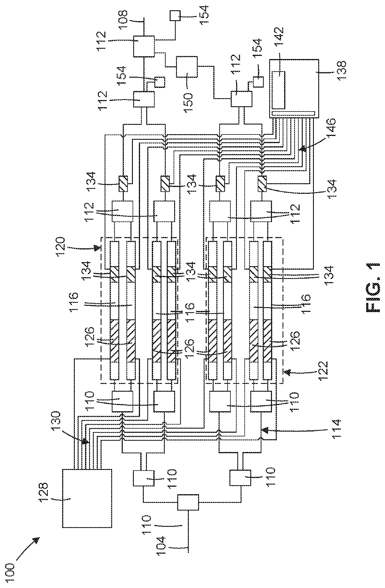
[0010]To improve signal fidelity from an optical telecommunications transmitter, automatic bias control can be implemented to adjust for bias fluctuations without operator intervention. Bias drift can result in deteriorated signal quality from the transmitter. Feedback control can be used to keep the bias within acceptable ranges. The designs herein are particularly suitable for a coherent modulator, such as an optical modulator designed around dual-polarization N-Quadrature Amplitude Modulation (QAM), where N is the number of symbols in the modulation constellation of the digital modulation system. For the modulator, in certain embodiments, there are generally twelve points of bias control along the optical waveguides. Specifically, these are the I, Q, and φ branches of the MZI for each of the X and Y components, as explained further below.
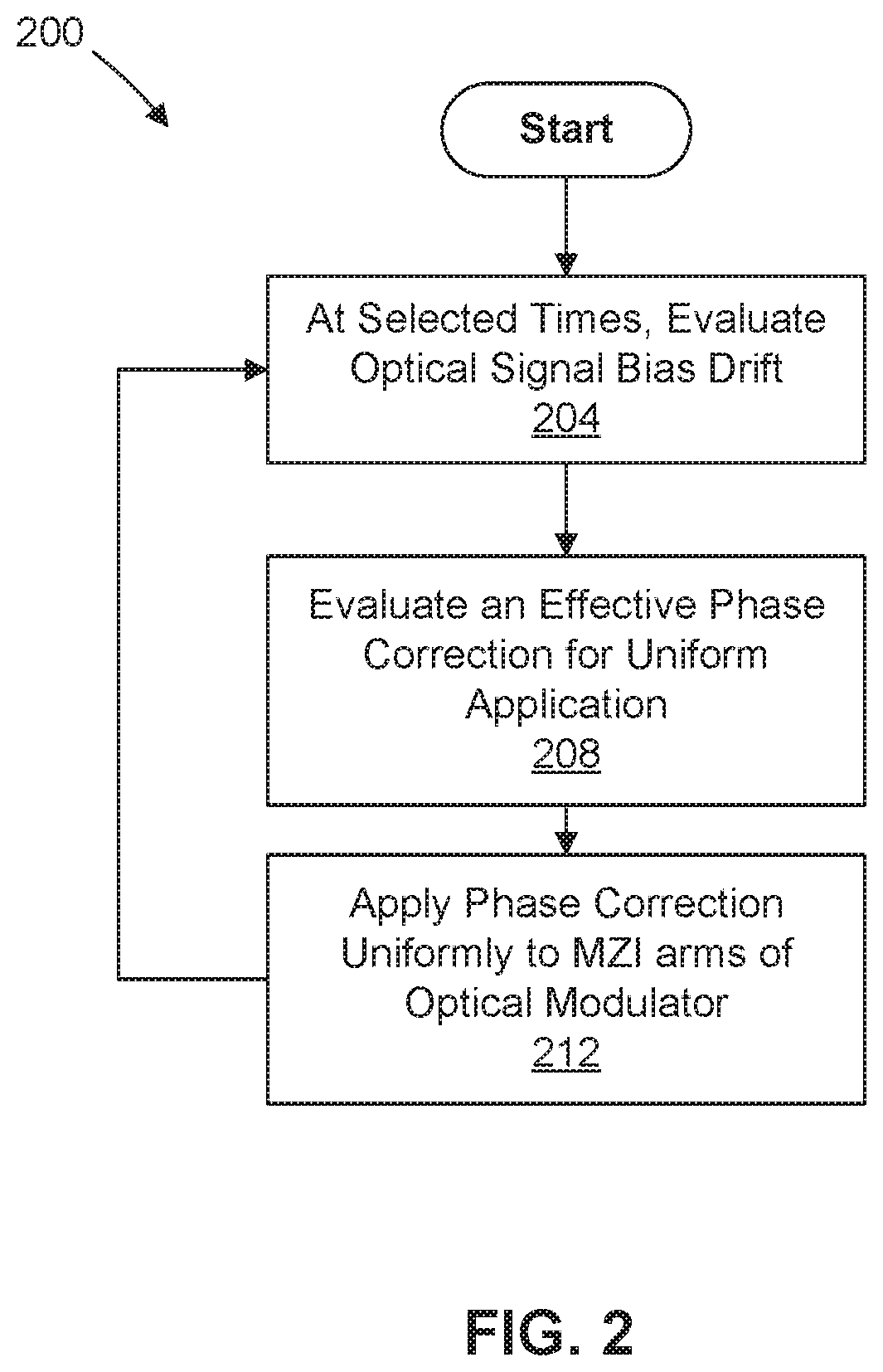
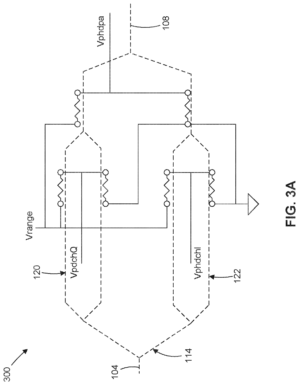
[0011]Coherent optical modulators comprise modulated signals in each of two polarization states. The two modulated polarizations are combined for directing the signal to the transmitter output. Each polarization state for QAM is modulated based on two phase shifted components, the in-phase (I component) and the quadrature phase (Q component). To modulate each of the phase components (I and Q), a Mach-Zehnder interferometer is used with RF modulation. For each polarization, a further MZI structure is used for each of the I and Q components to introduce modulation of these components. Thus, in one or more embodiments, each polarization can involve 3 MZI (I, Q, and I&Q) for a total of 6 MZI with 12 MZI arms since there are two for each. As described herein, in various embodiments the bias correction can be applied uniformly to all 12 MZI arms. Application of the bias correction in this way accounts for a majority of the bias correction while providing a significantly simplified system.
[0013]As such, the approach herein based on thermal phase adjustment and uniform phase adjustment across the 12 MZI arms provides the following advantages:
[0015]Maximum active power dissipation due to phase shifter heaters can be reduced (π / (2π+φa) if direction of aging can be predicted;

Problems solved by technology

When recombined, the optical signals then interfere with one another based on the Mach-Zehnder interferometer structure.
High fidelity transfer of the RF signal into modulation of the optical signal becomes more challenging as the frequency of the RF signal increases to accommodate higher bandwidth in the optical signal.

Method used


Image

  • Indium phosphide based optical transmitter with single parameter driven phase correction for temporal variation
  • Indium phosphide based optical transmitter with single parameter driven phase correction for temporal variation
  • Indium phosphide based optical transmitter with single parameter driven phase correction for temporal variation

Examples


Embodiment Construction

[0030]Referring to FIG. 1, a schematic layout of an optical subsystem including a coherent QAM based optical-RF modulator 100 is depicted, according to one or more embodiments. In various embodiments, the modulator 100 comprises an optical input waveguide 104 and optical output waveguide 108 that are connected through a series of optical splitters 110 and optical couplers 112 that split an input optical signal to direct the signal through a plurality of interconnected optical waveguides 114, including a plurality of nested Mach-Zehnder Interferometers (MZI) 116, each comprising optical semiconductor material. The modulator structure of FIG. 1 is consistent with an adopted standard, see FIG. 2.1 of Optical Internetworking Forum, Implementation Agreement for High Bandwidth Coherent Driver Modulator (HB-CDM), IA #OIF-HB-CDM 01.0, Nov. 30, 2018, incorporated herein by reference.

[0031]In one or more embodiments, the interconnected optical waveguides includes a first set 120 of MZI 166, s...


PUM

PropertyMeasurementUnit
voltageaaaaaaaaaa
optical phaseaaaaaaaaaa
opticalaaaaaaaaaa

Abstract

Optical modulators are described having a Mach-Zehnder interferometer and a pair of RF electrodes interfaced with the Mach-Zehnder interferometer in which the Mach-Zehnder interferometer comprises optical waveguides formed from semiconductor material. The optical modulator additionally comprises a plurality of phase shifters configured to interface with the plurality of interconnected optical waveguides such that at least one phase shifter of the plurality of phase shifters is interfaced with at least one optical waveguide of the plurality of interconnected optical waveguides. A phase shifter controller, including an energy source with a variable output controlled by the controller and a plurality of electrical connections connecting the energy source to each of the plurality of phase shifters, is also included. In various embodiments, the plurality of electrical connections are configured to provide approximately equal power to each of the phase shifting elements from the energy source.

Description

CROSS REFERENCE TO RELATED APPLICATIONS[0001]This application claims priority to U.S. provisional patent application 62 / 734,346 filed Sep. 21, 2018 to Giaretta et al., entitled “Indium Phosphide Based Optical Transmitter With Single Parameter Driven Phase Correction For Temporal Variation,” incorporated herein by reference.FIELD OF THE INVENTION[0002]The invention relates to optical modulators that can be useful in optical communications for various information transfer, and further relates to bias control of optical modulators that can be implemented to adjust for bias fluctuations without operator intervention.BACKGROUND[0003]Optical modulators incorporating Mach-Zehnder interferometer structures can be used to impose RF modulation on an optical signal, such as light from a laser source. The RF modulation can encode information within the optical signal for transport to remote locations through an optical communications network. The encoded information can include, for example, da...

Claims


Application Information

Patent Timeline
Patent Type & Authority Patents(United States)
IPC IPC(8): G02F1/225G02F1/21
CPCG02F1/2255G02F1/212G02F2202/102
Inventor GIARETTA, GIORGIOPIRASTU, ALESSIO
Owner NEOPHOTONICS CORP
Learn More