
Signal emitter location determination using sparse DOA estimation based on a multi-level prime array with compressed subarray

a subarray and sparse doa technology, applied in the field of antenna array systems, can solve the problems of increasing the number of antennas and the aperture size, combining several mras, and requiring large physical aperture sizes, so as to improve the signal reception, increase the number of estimated sources or the degree of freedom (dof), and improve the effect of signal reception

Active Publication Date: 2021-09-14
KING FAHD UNIVERSITY OF PETROLEUM AND MINERALS
View PDF5 Cites 0 Cited by
  • Summary
  • Abstract
  • Description
  • Claims
  • Application Information

AI Technical Summary

Benefits of technology

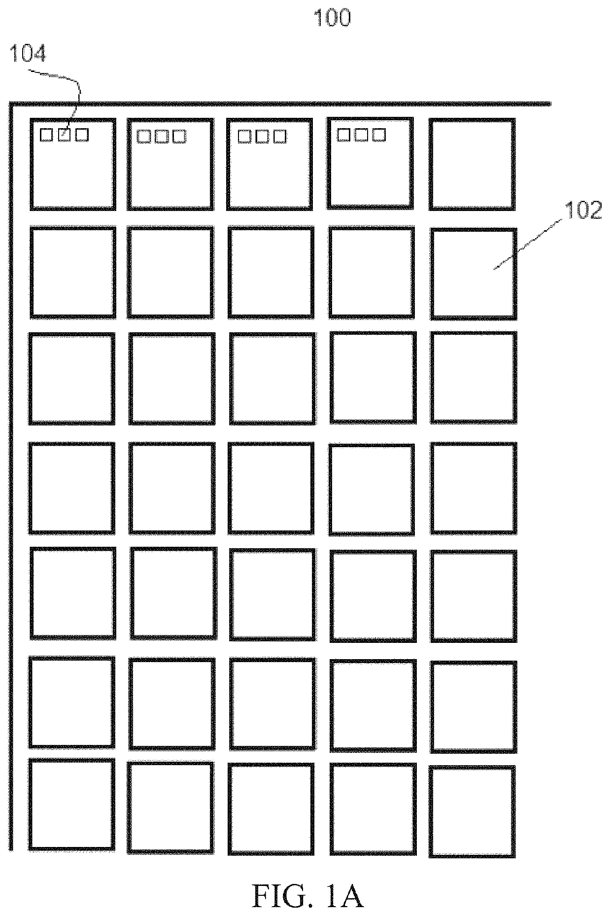
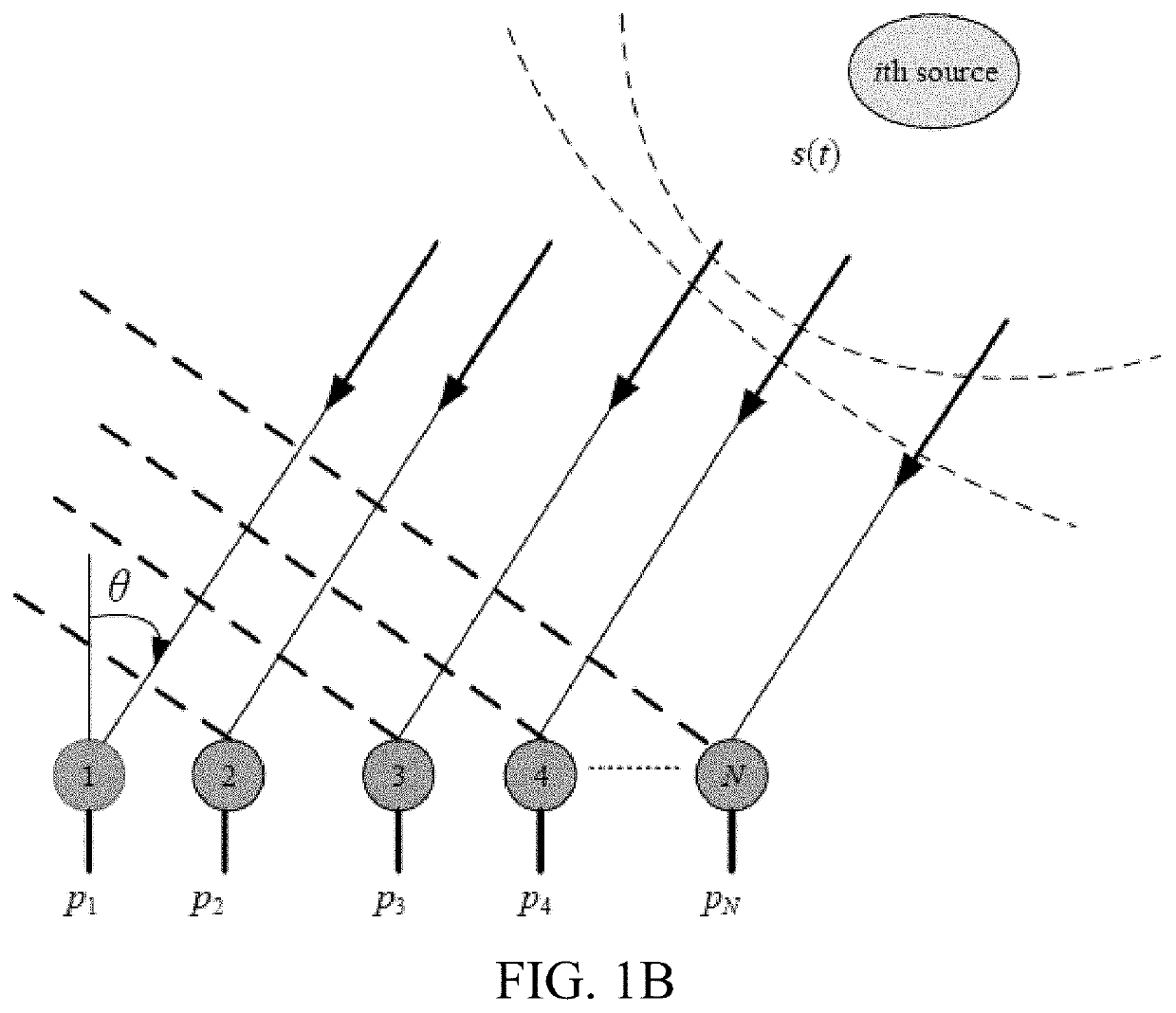
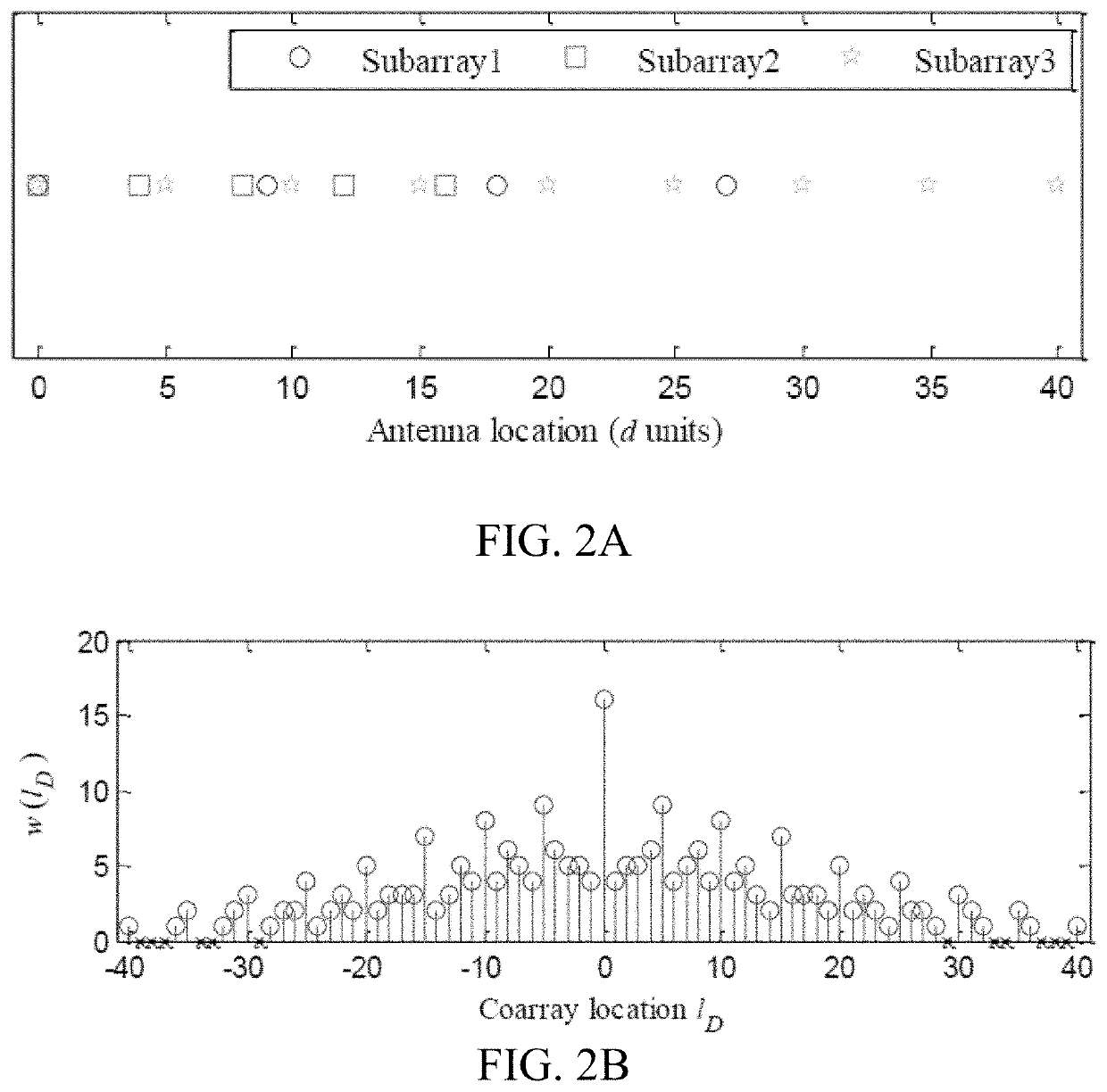
[0011]The present invention embodies sparse DOA estimation based on a multi-level prime arrays (MLPAs) as a general structure for coprime arrays. The array uses multiple uniform subarrays “or levels” where the number of antenna elements of the subarrays are pairwise coprime integers. The subarrays overlap only at their first antenna element by adjusting the inter-element spacing. By selecting the number of antennas of the subarrays and controlling the inter-element spacing, various MLPAs of different features can be constructed. The configuration that realizes the maximum number of unique lags is recommended because the DOF is upper bounded by the number of lags. The MLPA configuration is further optimized in order to increase the DOF by compressing the inter-element spacing of one subarray but without scarifying the number of antennas nor the aperture size. A proper selected compression factor and a specific subarray can maximize the number of lags and leads to a hole free difference co-array. It has been shown that large number of sources can be detected based on MLPA configurations using sparse reconstruction and MUSIC algorithms. In addition, MLPA configurations with compression can resolve larger number of sources compared with MLPAs due to upgrading the number of lags.

Problems solved by technology

However, combining several MRAs requires large physical aperture size.
This array improves the DOF but at the expense of increased the number of antennas and the aperture size.

Method used


Image

  • Signal emitter location determination using sparse DOA estimation based on a multi-level prime array with compressed subarray
  • Signal emitter location determination using sparse DOA estimation based on a multi-level prime array with compressed subarray
  • Signal emitter location determination using sparse DOA estimation based on a multi-level prime array with compressed subarray

Examples


Embodiment Construction

[0068]The embodiments of the present invention will be described herein below in conjunction with the above-described drawings.

[0069]The present disclosure includes a method for signal emitter location and an apparatus or system therefore. The method for determining the location of a signal emitter may be carried out on an apparatus or system that includes an antenna array that performs collects, receives and / or analyzes narrow band or wide band signals and / or carries out direction finding. Examples of the antenna array include but are not limited to a linear antenna array, a planar antenna array, and the like. The system preferably includes a receiver that functions to receive signals acquired by the antenna array and passes the signals to one or more of a channel profiler and the direction finder.

[0070]The channel profiler may include a space channel divider, a single space channel profiler and / or a post channel profiler 306. The spatial channel divider preferably processes the si...


PUM


Abstract

A sparse DOA estimation is based on a multi-level prime arrays (MLPAs) as a general structure for coprime arrays. The array uses multiple uniform subarrays “or levels” where the number of antenna elements of the subarrays are pairwise coprime integers. The subarrays overlap only at their first antenna element by adjusting the inter-element spacing. By selecting the number of antennas of the subarrays and controlling the inter-element spacing, various MLPAs of different features can be constructed. The configuration that realizes the maximum number of unique lags is recommended because the DOF is upper bounded by the number of lags.

Description

STATEMENT OF ACKNOWLEDGEMENT[0001]The authors would like to acknowledge the support provided by the Deanship of Scientific Research (DSR) at King Fahd University of Petroleum & Minerals (KFUPM) for funding this work through project No. IN161015.SUMMARY OF THE INVENTIONField of the Invention[0002]This invention relates to an antenna array system which comprises a multilevel prime array (MLPA) configuration, wherein the array configuration comprises multiple uniform linear subarrays, wherein the number of elements in the subarrays is a pairwise coprime integer. The inter-element spacing of each subarray overlaps the first antenna element of the subarray, the inter-element spacing of one subarray is compressed to optimize the MLPA configuration, and the inter-element spacing is compressed under fixed number of antennas (N) and a fixed aperture size (D). The invention further relates to a method of optimizing the antenna array system by maximizing the number of consecutive lags and mini...

Claims


Application Information

Patent Timeline
Patent Type & Authority Patents(United States)
IPC IPC(8): G01S5/06G01S1/02G01S7/282G01S13/87
CPCG01S5/06G01S1/024G01S7/282G01S13/878G01S3/043G01S3/74G01S5/02G01S5/0221G01S5/0252
Inventor ALAWSH, SALEH AHMEDMUQAIBEL, ALI HUSSAIN
Owner KING FAHD UNIVERSITY OF PETROLEUM AND MINERALS
Learn More