
Gravitationally directed conveyor material cleat

a gravity-directed conveyor and material cleat technology, applied in the direction of conveyors, transportation and packaging, etc., can solve the problem of requiring limitation

Active Publication Date: 2021-09-14
CLEASBY LLC
View PDF13 Cites 1 Cited by
  • Summary
  • Abstract
  • Description
  • Claims
  • Application Information

AI Technical Summary

Benefits of technology

The patent describes a device that can be raised and lowered to move materials from one location to another. The device has a unique design that allows it to be easily raised and lowered with minimal effort. In the raised position, the device has a low profile that can fit within a conveyor boom. The bottom part of the device is in the same position as the material being transported, making it easier to interfacing with the materials. Overall, the device is designed to make the material movement process easier and more efficient.

Problems solved by technology

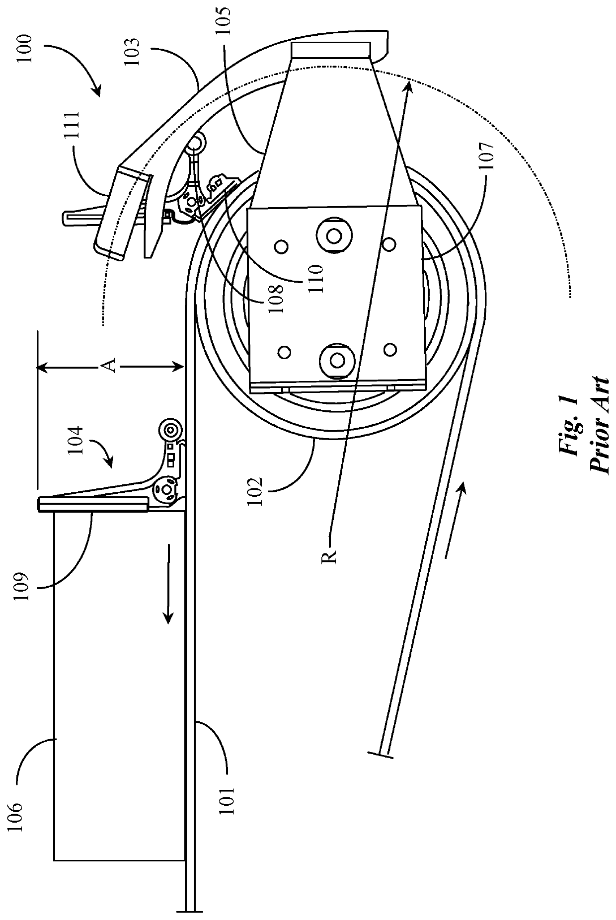
There are drawbacks to this system relative to height limitations for the cleats.
The limitation is required due to the fact that there is only enough clearance on the return side of the conveyer that runs through the housing and frame elements for a cleat no more than 3 inches in height.
A downside to this approach is the complexity of the pin contact apparatus and meticulous positioning of the apparatus, as well as the fact that once the cleats in a pair leave the flip tracks they immediately spring back into the prone position so a load of material must be positioned to catch the material surfaces of the cleats while they are still being held vertical by ramps.

Method used


Image

  • Gravitationally directed conveyor material cleat
  • Gravitationally directed conveyor material cleat
  • Gravitationally directed conveyor material cleat

Examples


Embodiment Construction

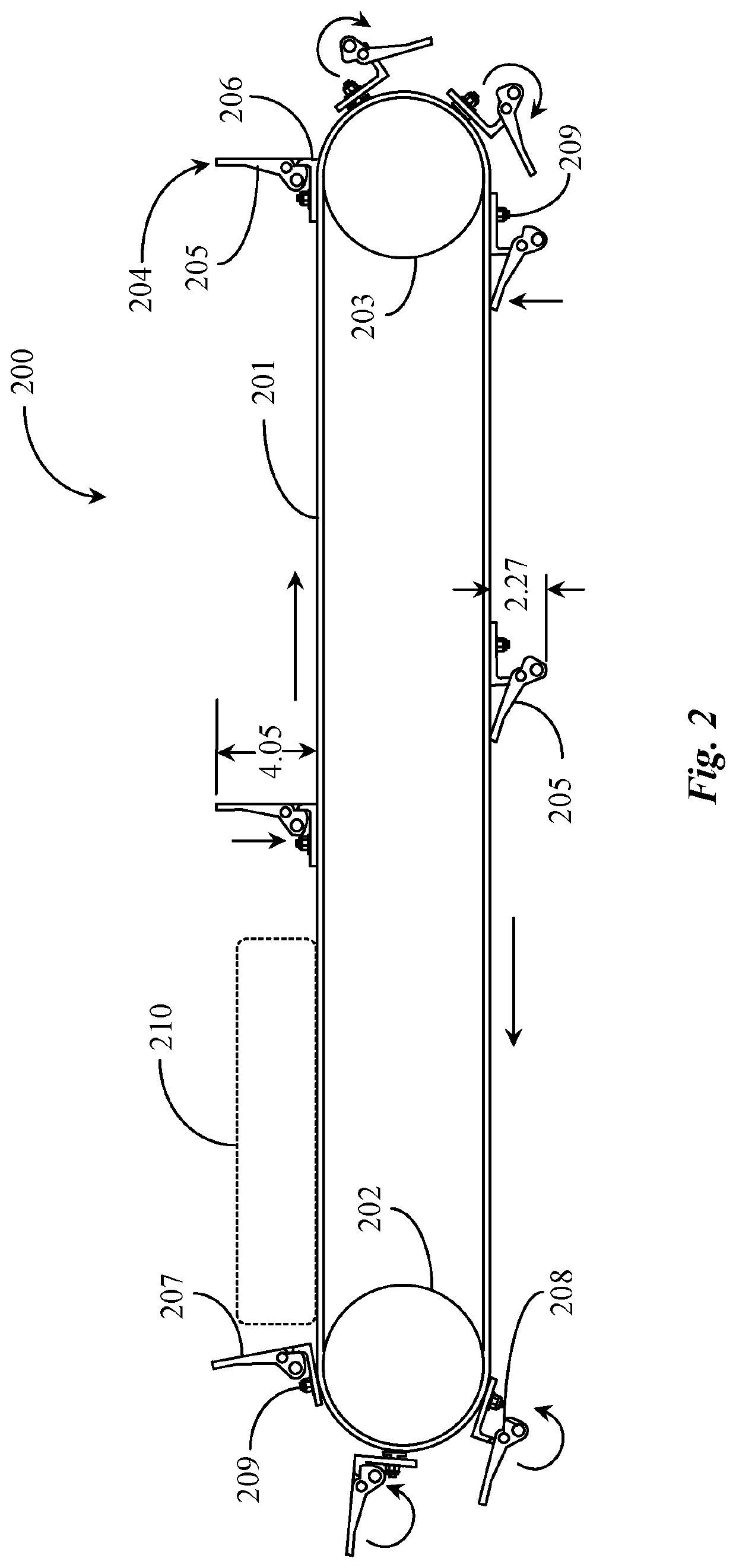
[0022]In various embodiments described in enabling detail herein, the inventor provides a unique system of material cleats that change position based on gravitational direction based on the angle of presentation on a material conveyor. A goal of the present invention is to provide a height-adjustable cleat for ferrying materials on a material conveyor system without requiring external contact against a portion of the cleat in order to adjust position between upright and prone. The present invention is described using the following examples, which may describe more than one relevant embodiment falling within the scope of the invention.

[0023]FIG. 1 is a partial side-elevation view of a material conveyor 100 with position-adjustable material cleats according to current art. Material conveyer 100 is depicted in this partial view in the portion of the tail pulley end of conveyer 100. Tail pulley 102 supports a conveyer belt 101. In this view, the forward direction of belt 101 is indicate...


PUM


Abstract

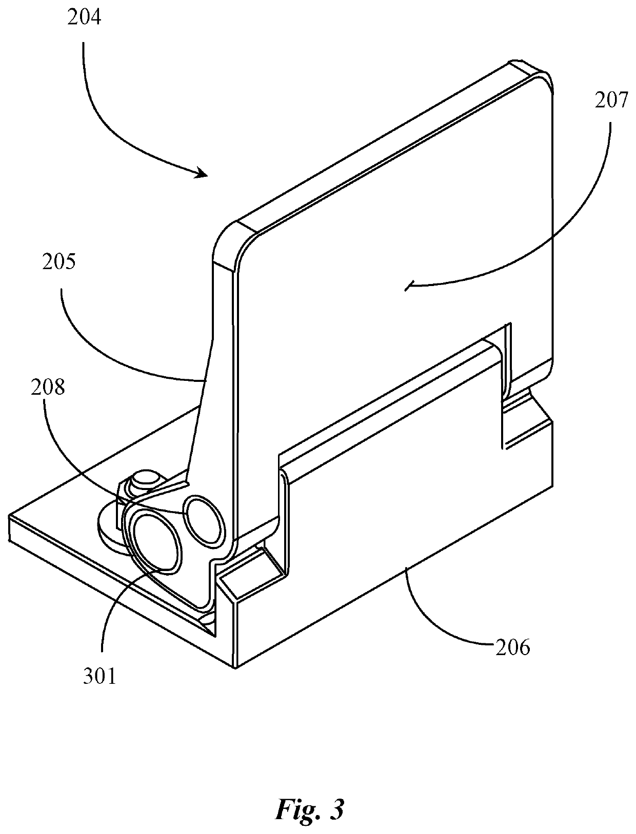
A cleat for ferrying materials on a conveyor belt line includes a top portion having a height, a width, and an overall material thickness, a material interfacing side, and a lateral opening extending there through for accepting a pin axle. A bottom portion having a length, a width, and material thickness, and a vertically extending wall, the bottom portion supporting the pin axle in a fixed manner, and a counter weight encapsulated in, embedded in, or attached to a lower portion of the top portion on the gravity side of the pin axle opening. The cleat top portion rotating to an upright position on the top of the conveyor line and to a prone position on the bottom of the conveyor line.

Description

CROSS-REFERENCE TO RELATED DOCUMENTS[0001][NA]BACKGROUND OF THE INVENTION1. Field of the Invention[0002]The present invention is in the field of construction equipment and pertains particularly to methods and apparatus for conveying materials onto and from a rooftop.2. Discussion of the State of the Art[0003]In the field of construction equipment, more particularly in the roofing industry, roofing materials have traditionally been carried or lifted onto a rooftop manually by the workers without any mechanical assistance. More recently, conveyor type systems including those that are hydraulically powered have been developed and used to convey heavy roofing materials such as roofing shingles for example from a ground location to the rooftop location where those materials will be applied in construction.[0004]One such system is known to the inventor and is included herein at least by reference to U.S. Pat. No. 5,984,077 granted for a mobile overhead conveyor system. This system as know...

Claims


Application Information

Patent Timeline
Patent Type & Authority Patents(United States)
IPC IPC(8): B65G17/16B65G15/58B65G15/44
CPCB65G17/16B65G15/44B65G15/58
Inventor DE GRAW, DARREN LPORTER, CHAD TYLER
Owner CLEASBY LLC
Learn More