Eureka AIR delivers breakthrough ideas for toughest innovation challenges, trusted by R&D personnel around the world.

Robot cleaner

a robot cleaner and cleaner technology, applied in the field of robot cleaners, can solve the problems of deteriorating cleaning efficiency, difficult to gain the effect of wet cloth mopping, and the inability of conventional robot cleaners to inject water into the mop pad, so as to increase the friction force, enhance the cleaning effect, and increase the friction for

Active Publication Date: 2021-09-07
LG ELECTRONICS INC
View PDF29 Cites 1 Cited by
  • Summary
  • Abstract
  • Description
  • Claims
  • Application Information

AI Technical Summary

Benefits of technology

[0048]The embodiments have following advantageous effects. The robot cleaner performs wet-cleaning, using water, and the foreign substances stuck to the floor may be mopped and removed.
[0049]Furthermore, the robot cleaner may increase the friction force with the floor and the cleanness of the wet-cleaning may be enhanced. In other words, the wet member is attached to the rotary wheel and the wheel is rotated. Accordingly, the member for we-cleaning not just passing the floor may create the effect of hand-mopping and scrubbing
[0050]Still further, the water tank holding water may be overlapped with the member for mopping the floor and the load of the water tank is applied to the member to increase the friction force when performing wet-cleaning. Accordingly, the performance of the wet-cleaning may be enhanced.
[0051]After performing wet-cleaning for the floor, the moisture or water remaining the floor may be removed and water stains may be prevented. After the soaked member performs the wet-cleaning, the dry member performs cleaning for the floor and performs double-cleaning for the same floor or cleaning object surface.
[0052]Using the centrifugal force generated by the rotation of the wheel, water may be uniformly distributed to the member for the wet-cleaning for the floor and the moisture content percentage of the wet member may be adjusted properly.
[0053]The robot cleaner may acquire accurate information for the location of the cleaner body by using external signal for locating the cleaner body.

Problems solved by technology

However, such a conventional robot cleaner cannot inject water to the mop pad.
It is difficult to gain the wet-cloth-mopping-like function, if using the conventional robot cleaner having the microfiber or fabric mop pad.
When the conventional robot cleaner moves with pushing the mop pad, a sufficient friction force fails to be applied to the mop pad and then a disadvantage of deteriorated cleaning efficiency might arise.

Method used


Image

  • Robot cleaner
  • Robot cleaner
  • Robot cleaner

Examples


Embodiment Construction

[0064]Referring to the accompanying drawings, exemplary embodiments of the present disclosure according to one embodiment of the present disclosure will be described in detail.

[0065]Regardless of numeral references, the same or equivalent components may be provided with the same reference numbers and description thereof will not be repeated. For the sake of brief description with reference to the drawings, the sizes and profiles of the elements illustrated in the accompanying drawings may be exaggerated or reduced and it should be understood that the embodiments presented herein are not limited by the accompanying drawings.

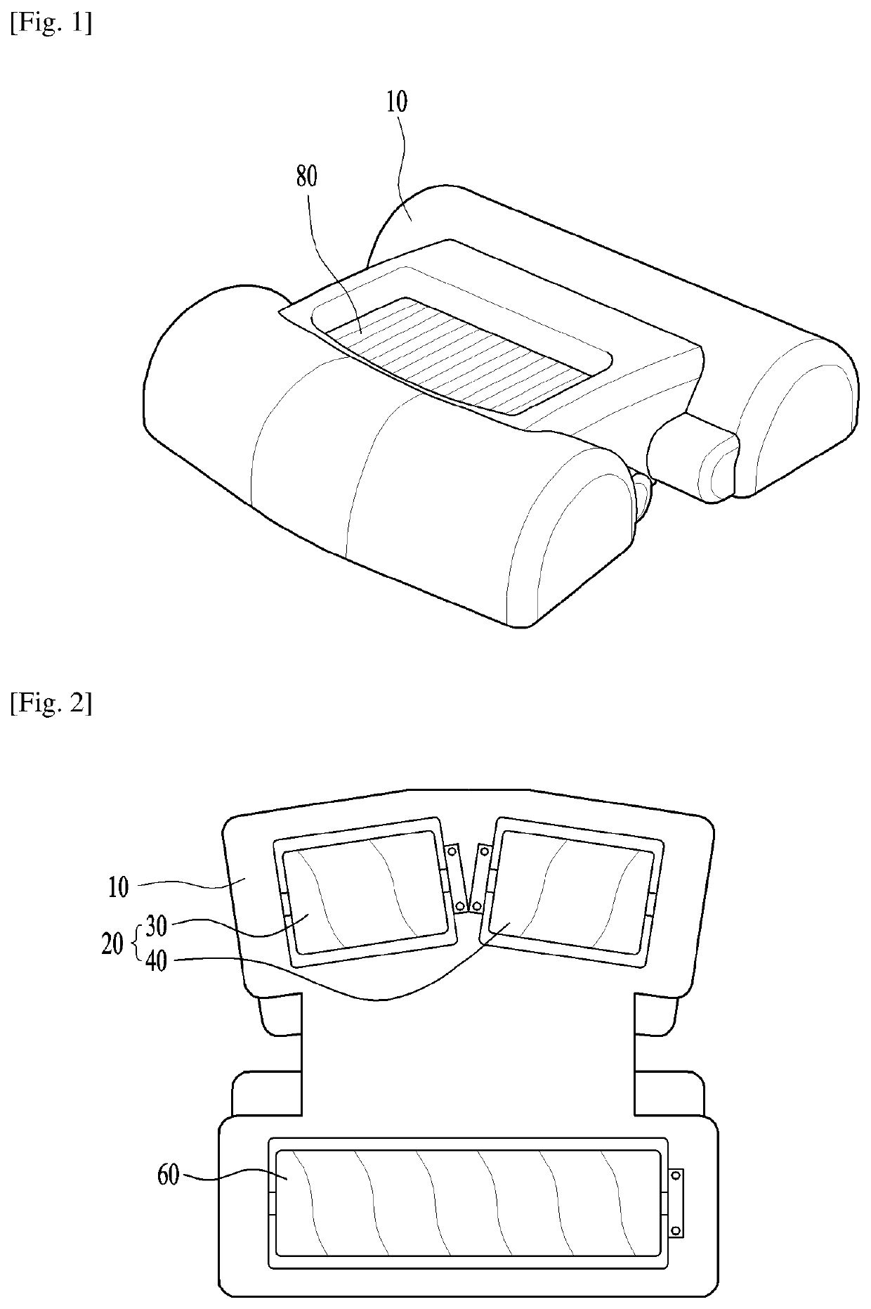
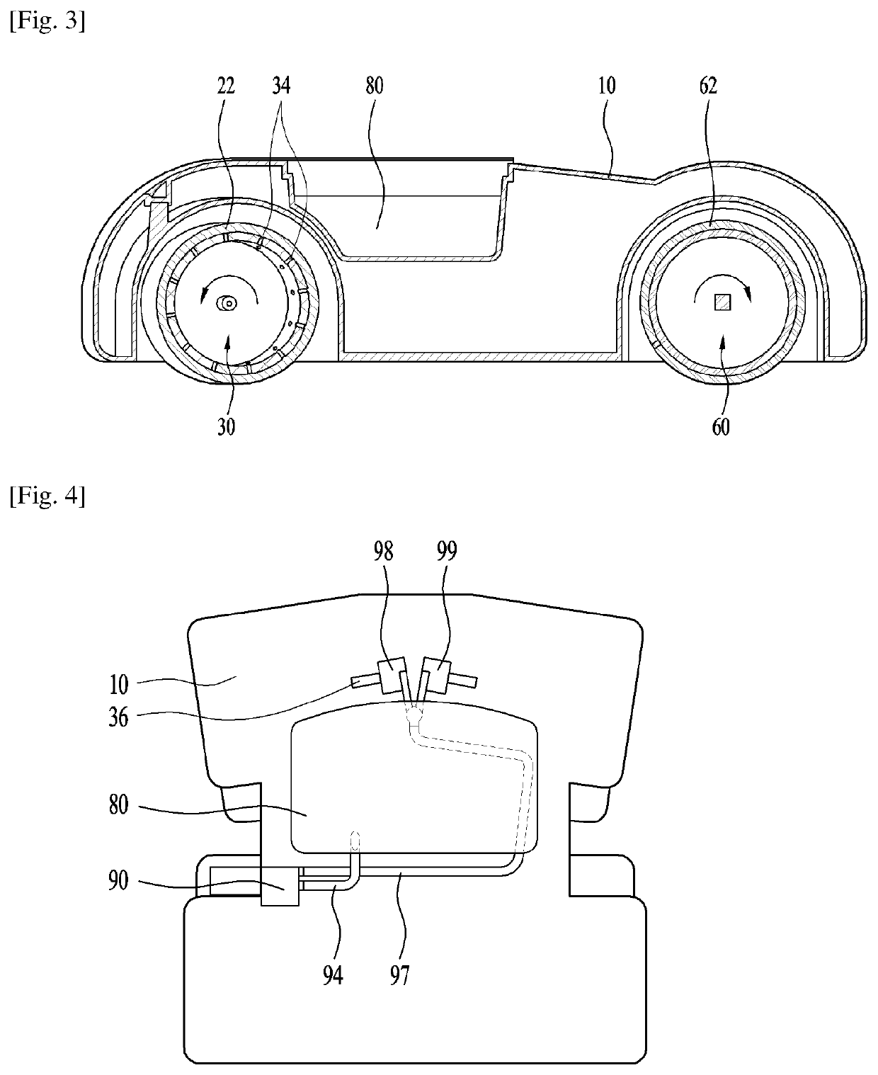
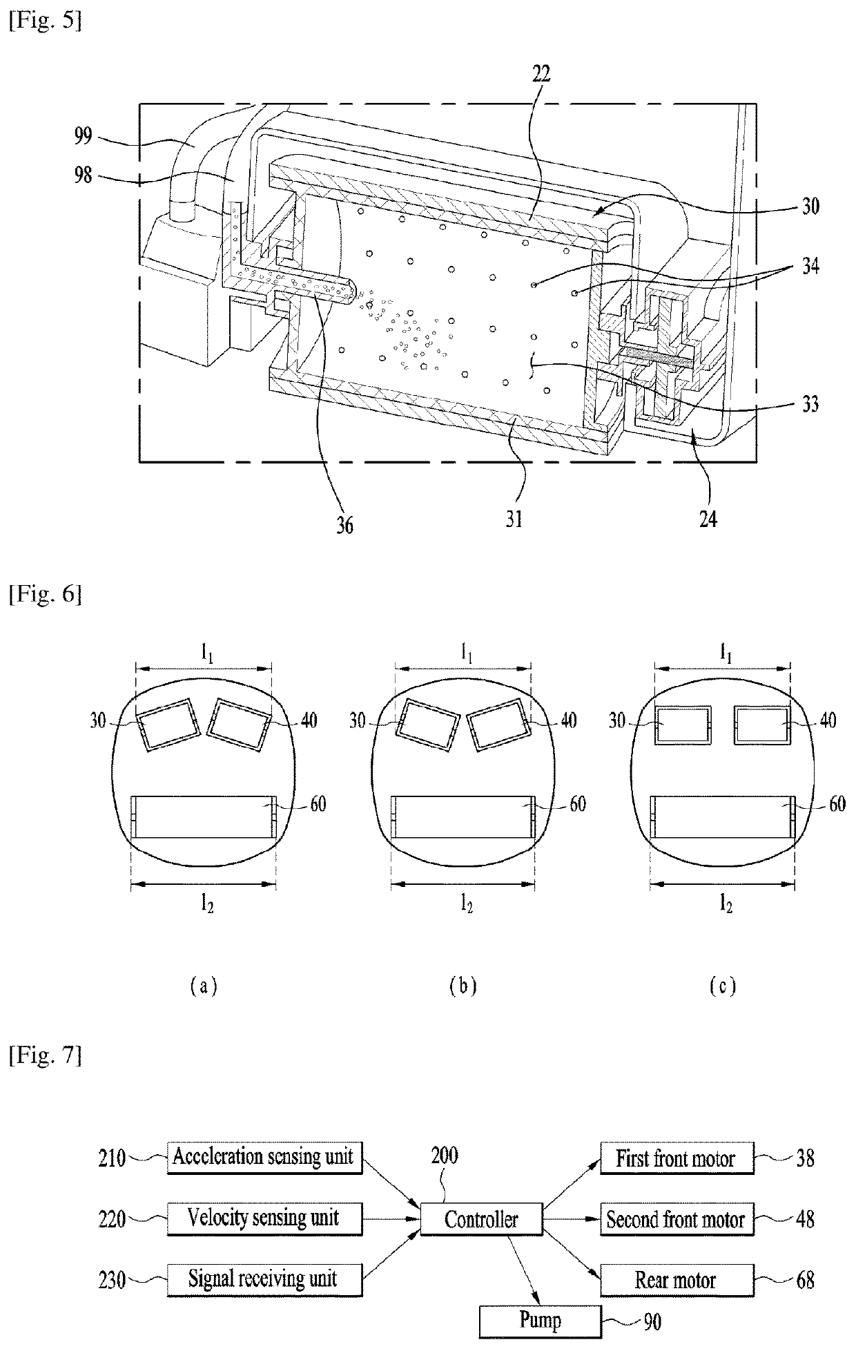
[0066]FIG. 1 is a perspective diagram illustrating one embodiment of the present disclosure and FIG. 2 is a diagram illustrating a low area of FIG. 1. FIG. 3 is a side sectional diagram of FIG. 1 and FIG. 4 is a diagram illustrating key parts of FIG. 1. FIG. 5 is a diagram illustrating a front wheel.

[0067]Referring to FIGS. 1 through 5, a robot cleaner in accordan...


PUM


Abstract

Disclosed is a cleaner comprising a cleaner body, a front wheel rotatably provided in a front portion of the cleaner body, a rear wheel rotatably provided in a rear portion of the cleaner body, a first member attached to an outer circumferential surface of the front wheel and configured to contact with a cleaning object surface, a second member attached to an outer circumferential surface of the rear wheel and configured to contact with the cleaning object surface, a front motor rotating the front wheel, a rear motor rotating the rear wheel and a controller driving the front motor and the rear motor, wherein the controller controls the front motor and the rear motor to become rotated in the opposite directions while cleaning is performed.

Description

CROSS-REFERENCE TO RELATED PATENT APPLICATIONS[0001]This application is a U.S. National Stage Application under 35 U.S.C. § 371 of PCT Application No. PCT / KR2016 / 010541, filed Sep. 21, 2016, which claims priority to Korean Patent Application No. 10-2015-0134514, filed Sep. 23, 2015, whose entire disclosures are hereby incorporated by reference.TECHNICAL FIELD[0002]Embodiments of the present disclosure relate to a robot cleaner, more particularly, to a robot cleaner which is capable of cleaning floors, using water.BACKGROUND ART[0003]A conventional robot cleaner is the mechanism put into operation by a battery power and configured to become automatically mobile according to a command of a micro-computer implemented for controlling a cleaning system based on sensor information and program logic.[0004]In addition, the conventional robot cleaner is usually configured to perform a cleaning function by sucking the dust that is scattered there below on the floor along a route, using fan su...

Claims


Application Information

Patent Timeline
Patent Type & Authority Patents(United States)
IPC IPC(8): A47L11/40A47L11/18A47L11/19A47L11/29
CPCA47L11/4011A47L11/185A47L11/19A47L11/29A47L11/408A47L11/4041A47L11/4072A47L11/4083A47L2201/028A47L2201/04A47L2201/06
Inventor JANG, JAEWONKIM, JEONGYUNYANG, INHYUNG
Owner LG ELECTRONICS INC
Why Eureka
Eureka Blog
Learn More