Cooling system and cooling method

a technology of cooling system and cooling method, which is applied in the direction of cooling/ventilation/heating modification, basic electric elements, electrical apparatus, etc., can solve the problems of damage to the electrical insulation of the conductor, and achieve the effect of reducing power consumption, reducing power consumption, and increasing cooling ra

Active Publication Date: 2021-08-31
HITACHI ENERGY LTD
View PDF16 Cites 2 Cited by
  • Summary
  • Abstract
  • Description
  • Claims
  • Application Information

AI Technical Summary

Problems solved by technology

The windings of a high voltage electromagnetic induction devices are often subjected to currents that result in heat development in the windings that would damage the electrical insulation of the conductors, and even the conductors, if cooling of the windings would not be provided.
But, the solution according to the patent has disadvantage that a sum of the power consumption by the operating fans is not considered so it may be is relatively high, which accomplish a predetermined amount of cooling capacity.

Method used


Image

  • Cooling system and cooling method
  • Cooling system and cooling method
  • Cooling system and cooling method

Examples


Embodiment Construction

[0017]While the invention is susceptible to various modifications and alternative forms, specific embodiments thereof are shown by way of example in the drawings and will herein be described in detail. It should be understood, however, that the drawings and detailed description thereto are not intended to limit the invention to the particular form disclosed, but on the contrary, the intention is to cover all modifications, equivalents, and alternatives falling within the spirit and scope of the present invention as defined by the appended claims. Note, the headings are for organizational purposes only and are not meant to be used to limit or interpret the description or claims. Furthermore, note that the word “may” is used throughout this application in a permissive sense (i.e., having the potential to, being able to), not a mandatory sense (i.e., must).” The term “include”, and derivations thereof, mean “including, but not limited to”. The term “connected” means “directly or indire...


PUM

PropertyMeasurementUnit
temperaturesaaaaaaaaaa
cooling capacityaaaaaaaaaa
temperatureaaaaaaaaaa

Abstract

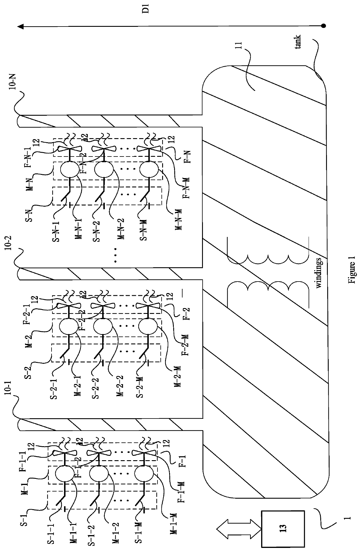
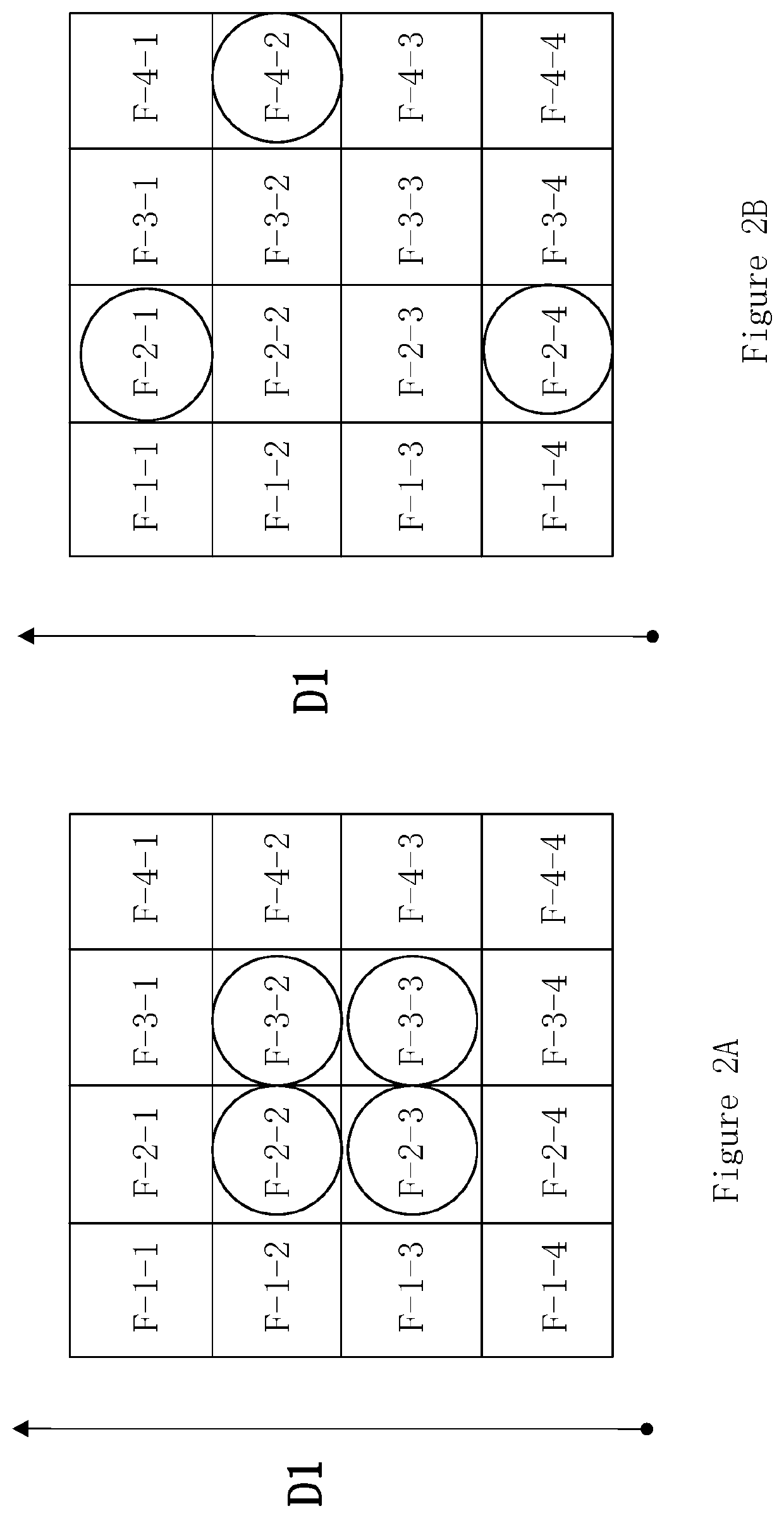
A cooling system for a high voltage electromagnetic induction device, includes: at least one duct filled with a first coolant and surrounded by a second coolant, each being routed along a direction of natural convection; at least one group of fans, each fan of the group being mounted along a respective duct of the at least one duct along the direction of natural convection and being configured to blow for the-second-coolant-forced cooling; at least one group of electric motors, each electric motor being configured to operate a respective fan of the at least one group of fans; at least one group of switches, each switch being configured to control a respective electric motor of the at least one group of electric motors. A method of cooling a high voltage electromagnetic induction device is also provided. By using the option of operating fans with higher cooling rate, because of the less fans are operating, the predetermined cooling capacity can be reached with lower power consumption.

Description

TECHNICAL FIELD[0001]The invention relates to control of temperature of a power equipment, and more particularly to control of temperature of a high voltage electromagnetic induction device, with digital data processing.BACKGROUND ART[0002]High voltage electromagnetic induction devices, such as power transformers, comprise windings, typically electrically insulated conductors, wound around a magnetic core. The windings of a high voltage electromagnetic induction devices are often subjected to currents that result in heat development in the windings that would damage the electrical insulation of the conductors, and even the conductors, if cooling of the windings would not be provided.[0003]There are a number of ways in which a high voltage electromagnetic induction device may be cooled. Cooling may for example be performed by means of natural or forced convection of a liquid such as oil circulating through the tank of high voltage electromagnetic induction device. For higher voltages...

Claims


Application Information

Patent Timeline
Patent Type & Authority Patents(United States)
IPC IPC(8): H01F27/08H05K7/20
CPCH05K7/20145H01F27/085H05K7/20127
Inventor YU, RONGRONGSAERS, ROBERTLANERYD, TOR
Owner HITACHI ENERGY LTD
Why Eureka
Try Eureka