Stator for rotating electric machine, and rotating electric machine

a technology of rotating electric machines and statators, which is applied in the direction of stator/rotor bodies, magnetic circuit rotating parts, and shape/form/construction of magnetic circuits, etc., can solve the problems of performance degradation, inability to avoid magnetic flux leakage between adjacent teeth via the connection portion, etc., to reduce the cross-sectional area of the core at the connection portion, reduce the effect of leakage magnetic flux and magnetic resistan

Active Publication Date: 2021-08-17
MITSUBISHI ELECTRIC CORP
View PDF4 Cites 0 Cited by
  • Summary
  • Abstract
  • Description
  • Claims
  • Application Information

AI Technical Summary

Benefits of technology

[0021]In the stator for a rotary electric machine and the rotary electric machine according to the present invention, by providing a hole in each connection portion between the teeth, and splitting each connection portion into the outer side connection portion and the inner side connection portion, the cross-sectional area of the core at the connection portion can be decreased. Accordingly, the magnetic resistance at this portion increases, and the effect of reducing a leakage magnetic flux between the teeth adjacent to each other in the circumferential direction is achieved, so that the electromagnetic characteristics of the rotary electric machine can be improved. In addition, by increasing residual stress in the outer side connection portion and the inner side connection portion, a magnetic flux flowing between the adjacent teeth via the connection portion can be further reduced, and thus a stator for a rotary electric machine and a rotary electric machine that have high efficiency can be provided.
[0022]Moreover, by providing a hole in each connection portion and forming each connection portion with a frame structure in which at least two beams (the outer side connection portion, the inner side connection portion) are rigidly joined, the rigidity of the stator core against deformation within a stacking plane can be improved. Accordingly, the effect is achieved that the stator core becomes unlikely to deform, and, in addition, the natural frequency of the stator core improves, so that vibration and noise of the rotary electric machine become unlikely to occur.

Problems solved by technology

However, since inner end portions of the adjacent teeth are connected to each other in the circumferential direction, magnetic flux leakage between the adjacent teeth via the connection portion cannot be avoided.
Even though performance improvement is achieved by increasing the density of the winding as described above, performance deterioration occurs due to the magnetic flux leakage between the teeth.

Method used


Image

  • Stator for rotating electric machine, and rotating electric machine
  • Stator for rotating electric machine, and rotating electric machine
  • Stator for rotating electric machine, and rotating electric machine

Examples


embodiment 1

[0038]Hereinafter, a stator for a rotary electric machine and a rotary electric machine according to Embodiment 1 of the present invention will be described with reference to the drawings. In this description, unless otherwise particularly mentioned, the terms “axial direction”, “circumferential direction”, “radial direction”, “inner peripheral side”, “outer peripheral side”, “inner side”, and “outer side” refer to the “axial direction”, “circumferential direction”, “radial direction”, “inner peripheral side”, “outer peripheral side”, “inner side”, and “outer side” of a stator, respectively.

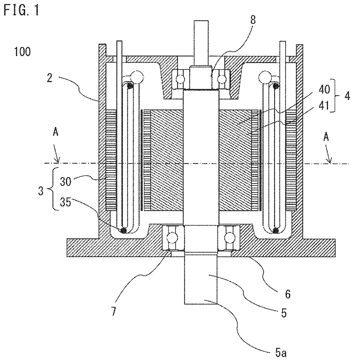
[0039]FIG. 1 is a schematic cross-sectional view of a rotary electric machine 100.

[0040]The rotary electric machine 100 is a brushless motor, has three or more phases, and includes a frame 2, a stator 3, a rotor 4, a rotation shaft 5, a bearing holder 6, a bearing 7, and a bearing 8. In the rotary electric machine 100, an output end side 5a of the rotation shaft 5 is referred to as front side, an...

embodiment 2

[0066]Hereinafter, a stator for a rotary electric machine and a rotary electric machine according to Embodiment 2 of the present invention will be described with reference to the drawing, focusing on the differences from Embodiment 1.

[0067]FIG. 8 is an enlarged perspective view of a main part of an inner core 230b.

[0068]In Embodiment 1, by providing the hole 32h in the connection portion 32 between the adjacent teeth 31, the connection portion 32 is configured to be split into the outer side connection portion 32a and the inner side connection portion 32b, so that a leakage magnetic flux is reduced and also the rigidity of the stator core 30 is increased. In the inner core 230b of the present embodiment, steel sheets K1 including a plurality of connection portions 32 and steel sheets K2 in which adjacent teeth 31 are not connected are alternately stacked. An air gap R is provided between the teeth 31 of the steel sheets K2 adjacent to each other in the circumferential direction.

[00...

embodiment 3

[0072]Hereinafter, a stator for a rotary electric machine and a rotary electric machine according to Embodiment 3 of the present invention will be described with reference to the drawing, focusing on the differences from Embodiment 1.

[0073]FIG. 9 is an enlarged perspective view of a main part of an inner core 330b.

[0074]Similar to Embodiment 1, the respective teeth 31 are connected at the inner side end portions thereof to the teeth 31 adjacent thereto in the circumferential direction by connection portions 332. Here, the width W1 in the radial direction of an outer side connection portion 332a and the width W2 in the radial direction of an inner side connection portion 332b are equal to or greater than ¼ and less than ½ of the sheet thickness T of each sheet forming a stator core.

[0075]As for the sheets that are electromagnetic steel sheets or steel sheets, sheets obtained by press working are used. The inner side surface and the outer side surface of the narrowest portion of the ...


PUM


Abstract

A stator core of a rotary electric machine includes: an outer core that is an annular back yoke portion; and an inner core in which a plurality of teeth are radially arranged and inner side end portions of the teeth adjacent to each other in a circumferential direction are connected to each other in the circumferential direction by connection portions and which is fitted to an inner side of the outer core, each connection portion has a hole penetrating in an axial direction, each connection portion is split into a plurality of sections by the hole, a width in a radial direction of the one connection portion at a portion of the connection portion that has a smallest width in the radial direction is equal to or greater than ¼ and less than ½ of a sheet thickness of each of sheets.

Description

TECHNICAL FIELD[0001]The present invention relates to a stator for a rotary electric machine and a rotary electric machine.BACKGROUND ART[0002]Hitherto, a method has been used in which, for a rotary electric machine in which a rotor is disposed at the inner peripheral side of a substantially cylindrical stator with a predetermined air gap therebetween, a stator core is divided into two sections, an inner core including teeth and an outer core that is a back yoke, a stator winding is installed into the inner core, and then the outer core is fitted thereto to integrate the stator core, which has been divided into two sections, thereby forming the stator.[0003]For such a rotary electric machine, winding can be performed, from the outer peripheral side, on the inner core including tooth portions, of the stator core divided into two sections. Thus, a wide work space can be taken at the time of winding as compared to a method in which winding is performed from the inner peripheral side of...

Claims


Application Information

Patent Timeline
Patent Type & Authority Patents(United States)
IPC IPC(8): H02K21/16H02K1/16H02K1/14H02K1/27H02K15/02H02K29/03
CPCH02K1/165H02K1/148H02K1/278H02K15/024H02K21/16H02K29/03H02K2213/03
Inventor KAWAMURA, KOJIHASHIMOTO, AKIRAAKITA, HIROYUKIKAWASAKI, SACHIKOMOTOISHI, NAOHIROMASUDA, TAKATOSHI
Owner MITSUBISHI ELECTRIC CORP
Why Eureka
Try Eureka