
Three dimensional infill in additive manufacturing

Active Publication Date: 2021-08-10
STRATSYS INC
View PDF27 Cites 0 Cited by
  • Summary
  • Abstract
  • Description
  • Claims
  • Application Information

AI Technical Summary

Benefits of technology

The present invention provides a way to create efficient and strong three-dimensional infill for interior spaces of articles. This helps to reduce the weight of the finished article while still providing sufficient strength. The invention also allows for adaptable and repeatable techniques for creating infill patterns in both regularly and irregularly shaped articles. Additionally, the invention allows for adjustments to be made quickly and reliably to address the need for additional infill in certain parts of a part. Overall, the invention improves the strength and efficiency of three-dimensional printed articles.

Problems solved by technology

There remain, however, many challenges in the design, manufacture, and use of 3D printers, as well as, in the advancement of 3D printing processes.

Method used


Image

  • Three dimensional infill in additive manufacturing
  • Three dimensional infill in additive manufacturing
  • Three dimensional infill in additive manufacturing

Examples


Embodiment Construction

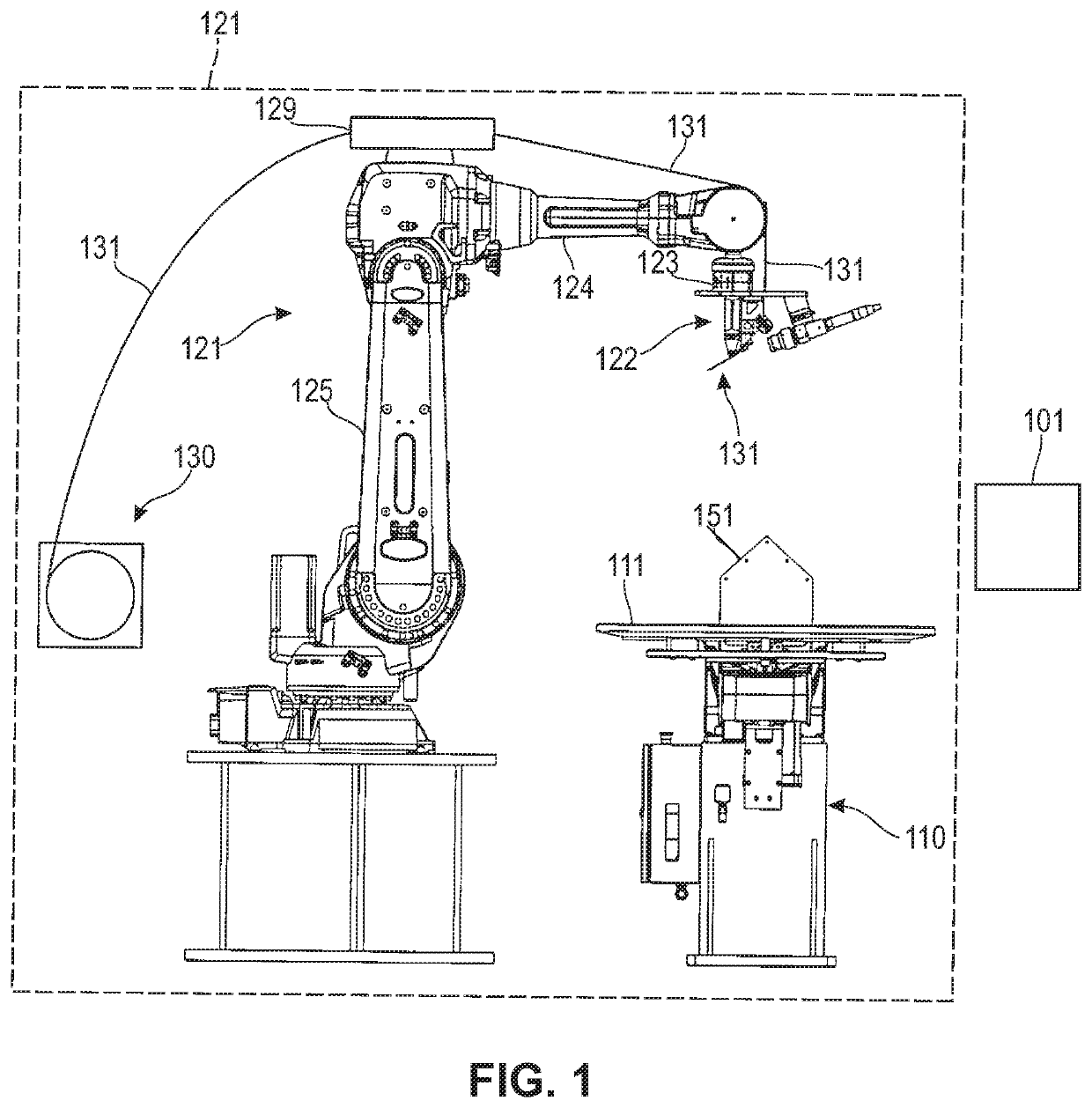
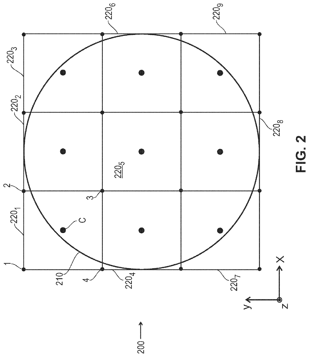
[0020]FIG. 1 depicts an illustration of the components of an exemplary additive manufacturing system 100 in accordance with the illustrative embodiments of the present invention. Additive manufacturing system 100 comprises: controller 101, turntable 110, deposition build plate 111, robot 121, deposition head 122, filament conditioning unit 129, filament source 130, and thermoplastic filament 131. The purpose of manufacturing system 100 is to fabricate articles of manufacture, such as illustrative article 151 of FIG. 1, as well as the articles of FIGS. 2-5 (a cylinder) and 7 (an irregularly shaped three dimensional object), for example. It will be recognized that the teachings of the present invention are applicable to a wide range of articles of manufacture, as well as materials, and the particular illustrations herein are exemplary.

[0021]Controller 101 comprises the hardware and software necessary to direct build chamber 102, robot 121, deposition head 122, and turntable 110, in or...


PUM

PropertyMeasurementUnit
lengthsaaaaaaaaaa
sizeaaaaaaaaaa
strengthaaaaaaaaaa

Abstract

An article of manufacture is disclosed that includes an infill generated utilizing three dimensional (3D) printing. Infill is generated utilizing segments of filament, such as, but not limited to continuous carbon fiber-reinforced thermoplastic filament. Other materials may also be suitably employed. Approaches to tool path generation which accomplish the 3D printing desired are addressed in which material runs of filament are applied that distribute where cuts, beginning, or ends of segments occur or points where ends of segments are anchored to the article to form the desired infill. Aspects of one approach include first generating a meta tool path for the infill and then adapting that tool path to an actual infill tool path by pruning any segments in the meta tool path extending outside the perimeter of the article and identifying anchor points to the article from observed intersections of the meta tool path and said perimeter.

Description

TECHNICAL FIELD[0001]The present invention relates generally to aspects of additive manufacturing of three-dimensional articles, and, more particularly, to improved techniques for fabricating articles of manufacture employing advantageous approaches to generate three dimensional infill as addressed further herein.BACKGROUND[0002]In general, there are two complementary approaches to fabricate an article of manufacture: additive manufacturing and subtractive manufacturing.[0003]Additive manufacturing involves aggregating material to form the desired article of manufacture. In contrast, subtractive manufacturing involves removing material to form the desired article of manufacture. In practice, many articles of manufacture are fabricated using a combination of additive and subtractive techniques.[0004]A form of additive manufacturing—colloquially known as “3D printing”—is the subject of intense research and development because it enables the fabrication of articles of manufacture with ...

Claims


Application Information

Patent Timeline
Patent Type & Authority Patents(United States)
IPC IPC(8): G05B19/4099B29C64/393B29C64/118G06F30/23B33Y80/00B33Y10/00B33Y30/00B33Y50/02
CPCB29C64/393B29C64/118G05B19/4099G06F30/23B33Y10/00B33Y30/00B33Y50/02B33Y80/00B29C70/382B33Y50/00B29C64/106G06F30/20
Inventor ZYDZIK, MAGDA HELENANANDU, SOHIL
Owner STRATSYS INC
Learn More