
3D printing of objects with optical functional surfaces

a technology of optical functional surfaces and objects, applied in the direction of additive manufacturing processes, lighting and heating apparatus, instruments, etc., can solve the problems of relatively low thermal conductivity and poor stability of photocurable materials to be useful for injection molding applications

Active Publication Date: 2021-07-27
SIGNIFY HLDG BV
View PDF16 Cites 0 Cited by
  • Summary
  • Abstract
  • Description
  • Claims
  • Application Information

AI Technical Summary

Benefits of technology

[0007]It is an object of the present invention to overcome this problem, and to provide a less complex way to achieve a 3D printed surface suitable for use as an optical functional surface.
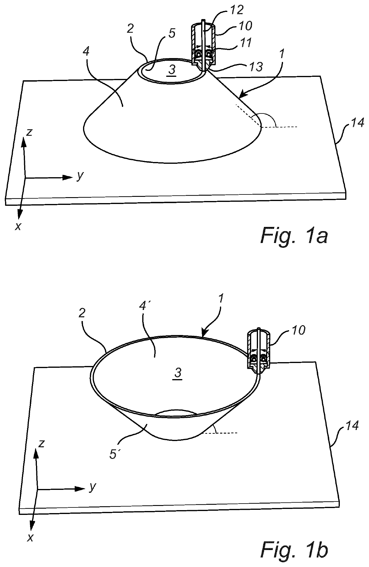
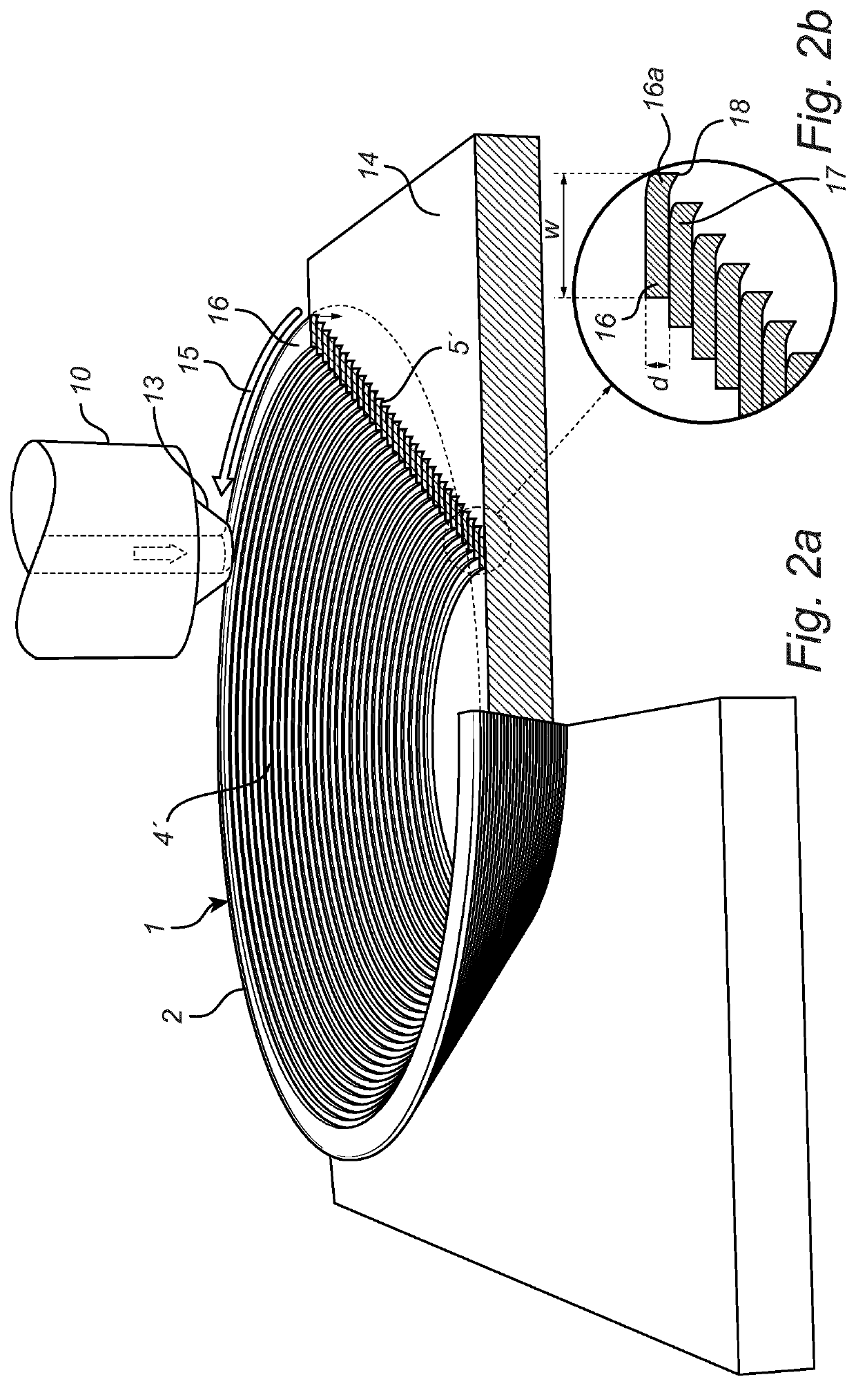
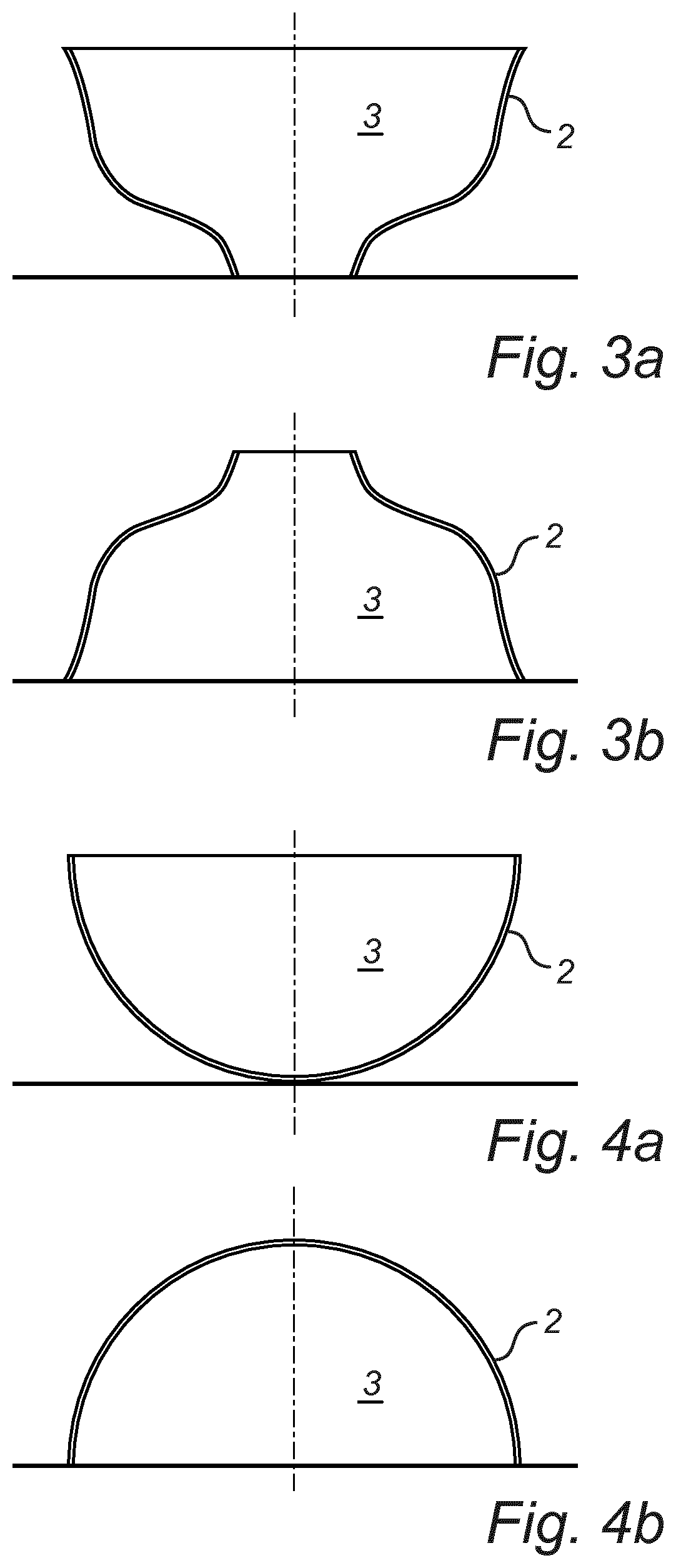
[0015]The present invention is based on the insight that when a non solid object including a wall formed by consecutive layers of printing material, the surface properties of this wall will depend on the orientation of the object during printing. If the wall is vertical (e.g. a vertical cylinder), the inside and outside surfaces of the wall will have the same roughness. However, when the wall is inclined with respect to the x-y plane, such as a tilted cylinder or a conical object, any surface facing the platform is rougher than the opposite surface facing away from the platform. The inventors have realized that by controlling the orientation of an object during printing, the surface quality of selected portions of the printed object can be controlled. In particular, an optical functional surface, e.g. a surface used for collimation of light or esthetics, may be oriented so that it is printed more smoothly than the opposite surface of the wall.
[0020]In some application, the smoothness obtained by ensuring the correct orientation during printing according to the present invention is sufficient. However, in other applications, the functional surface will be coated in order to obtain the desired properties. In this case, the smoother surface obtained by the present invention will be highly advantageous for such coating.

Problems solved by technology

While this technique produces smooth surfaces the photo curable materials are not very stable and they also have relatively low thermal conductivity to be useful for injection molding applications.

Method used


Image

  • 3D printing of objects with optical functional surfaces
  • 3D printing of objects with optical functional surfaces
  • 3D printing of objects with optical functional surfaces

Examples


Embodiment Construction

[0029]Currently preferred embodiments of the present invention will now be described in more detail, with reference to the accompanying drawings. The invention may, however, be embodied in many different forms and should not be construed as limited to the embodiments set forth herein; rather, these embodiments are provided for thoroughness and completeness, and fully convey the scope of the invention to the skilled person.

[0030]FIGS. 1a and 1b show FDM printing of an object 1, in the illustrated case in the shape of a cone. FDM printing is well known in the art, and will not be described in detail here. For the purpose of this disclosure, it is sufficient to say that an FDM printer has a printing head 10 including a feeder 11 for feeding a filament 12 of thermoplastic material through a channel in a nozzle 13. Immediately upstream of the nozzle is provided a heater (not shown) configured to heat the filament to its melting point, such that the thermoplastic is extruded and deposited...


PUM

PropertyMeasurementUnit
angleaaaaaaaaaa
angleaaaaaaaaaa
angleaaaaaaaaaa

Abstract

A method for 3D printing an object with at least one wall (2) having a first surface and a second, opposite surface, wherein the first surface is intended to serve as an optical functional surface, wherein the wall is formed by printing one track (16) on top of another track (17). An orientation of the object during printing is selected such that the wall has a tangent (or tangent surface) non-parallel to the z-axis, such that the first surface faces away from the x-y plane and the second surface faces the x-y plane. According to the invention, the 3D object is thus oriented during printing such that the first surface, intended to be used as an optical functional surface, faces away from the x-y plane, i.e. typically away from the support or platform on which the 3D object is printed upon. By ensuring this orientation during printing, the first surface becomes smoother than the second, opposite surface of the wall.

Description

CROSS-REFERENCE TO PRIOR APPLICATIONS[0001]This application is the U.S. National Phase application under 35 U.S.C. § 371 of International Application No. PCT / EP2016 / 076831, filed on Nov. 7, 2016, which claims the benefit of European Patent Application No. 15193623.4, filed on Nov. 9, 2015. These applications are hereby incorporated by reference herein.FIELD OF THE INVENTION[0002]The present invention relates to 3D printing of objects with at least one wall having a first surface and a second, opposite surface, wherein said first surface is intended to serve as an optical functional surface.BACKGROUND OF THE INVENTION[0003]Digital fabrication has begun to transform the nature of global manufacturing. One of the aspects of digital fabrication is 3D printing. Currently many different techniques have been developed in order to produce various 3D printed objects using various materials such as ceramics, metals and polymers. 3D printing can also be used in producing molds which can then b...

Claims


Application Information

Patent Timeline
Patent Type & Authority Patents(United States)
IPC IPC(8): B05D5/06B29D11/00B29C64/118B33Y10/00B33Y40/00G01S5/16B33Y80/00F21V1/26F21V7/04B29L31/00B29L11/00
CPCB29C64/118B05D5/063B29D11/0073B29D11/0074B33Y10/00B33Y40/00B33Y80/00F21V1/26F21V7/048G01S5/16B29L2011/00B29L2011/0083B29L2031/747B29L2031/7472B29C64/106
Inventor HIKMET, RIFAT ATA MUSTAFALIEDENBAUM, COEN THEODORUS HUBERTUS FRANSISCUS
Owner SIGNIFY HLDG BV
Learn More