Lever lock-type male connector and male connector assembly
a lever lock and connector technology, applied in the field of lever lock-type male connectors and male connector assemblies, can solve the problems of difficult release of screwed connections, thread breaking, and difficulty for users to accurately know the screwed state of male threads and female threads, and achieve excellent ease of operation for connection and disconnection.
- Summary
- Abstract
- Description
- Claims
- Application Information
AI Technical Summary
Benefits of technology
Problems solved by technology
Method used
Image
Examples
embodiment 1
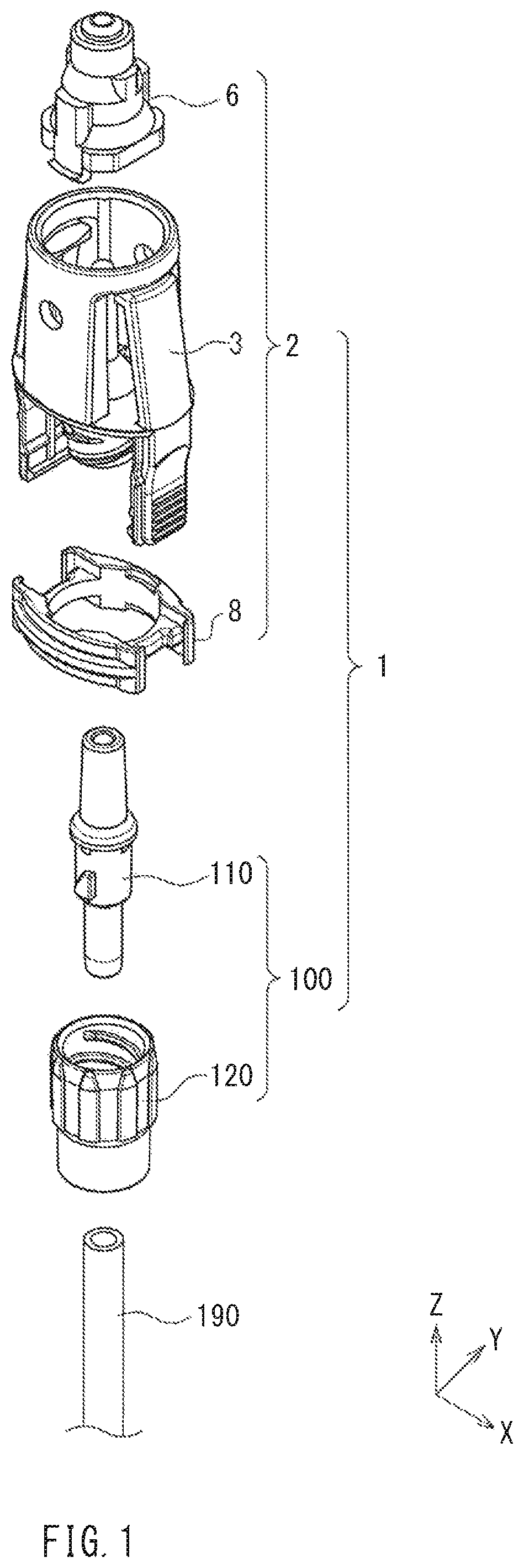
[0090]FIG. 1 is an exploded perspective view of a male connector assembly 1 according to Embodiment 1 of the present invention. The male connector assembly 1 includes a lever lock-type male connector (hereinafter simply referred to as “male connector”) 2 and a screw lock-type connector 100. The male connector 2 includes a connector main body 3, a shield 6, and a lock ring 8. The screw lock-type connector 100 includes a luer main body 110 and a lock nut 120. A flexible tube 190 is connected to the male connector 2 via the screw lock-type connector 100.
[0091]Hereinafter, the various portions will be sequentially described.
1. Male Connector
1. 1. Connector Main Body
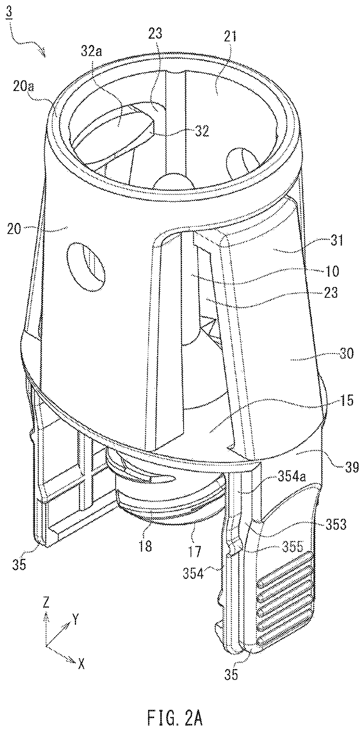
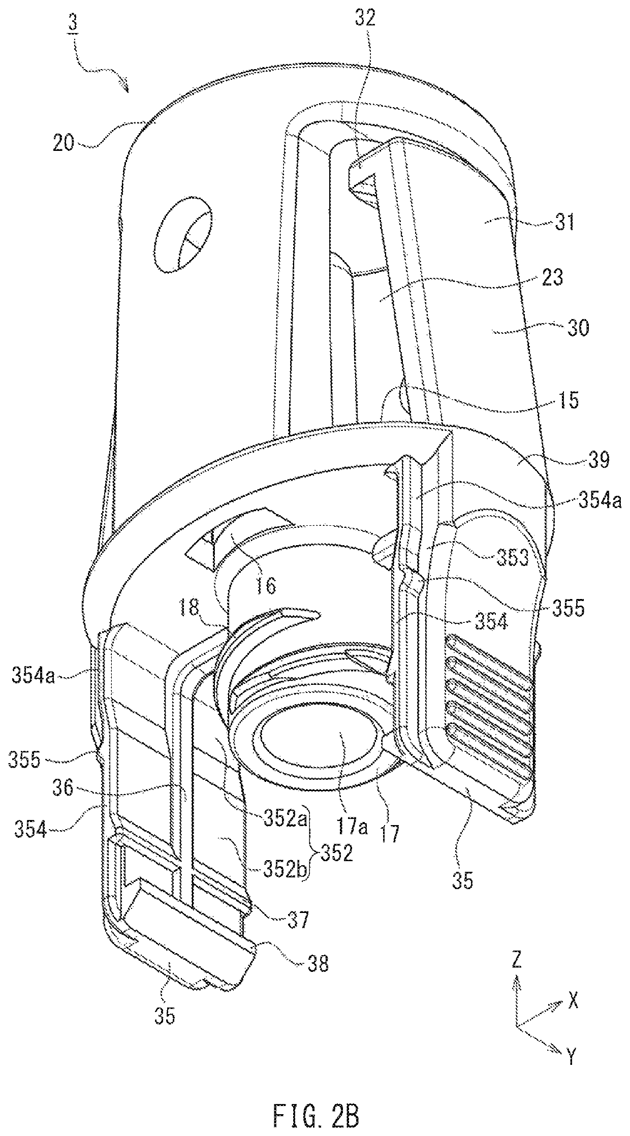
[0092]The connector main body 3 constituting the male connector 2 will be described. FIG. 2A is a perspective view of the connector main body 3 when viewed from above, and FIG. 2B is a perspective view of the connector main body 3 when viewed from below. FIGS. 2C, 2D, and 2E are a front view, a side view, and a plan view, in ...
embodiment 2
[0202]Embodiment 2 of the present invention differs from Embodiment 1 mainly in the configurations of the connector main body and the lock ring. Hereinafter, Embodiment 2 will be described focusing on the differences from Embodiment 1.
1. Connector Main Body
[0203]FIG. 14A is a perspective view of a connector main body 203 according to Embodiment 2 when viewed from above, FIG. 14B is a perspective view of the connector main body 203 when viewed from below, and FIG. 14C is a plan view of the connector main body 203. In FIGS. 14A to 14C, members corresponding to the members shown in FIGS. 2A to 2G are denoted by the same reference numerals as those in FIGS. 2A to 2G.
[0204]As can be easily understood by comparison of FIG. 14C with FIG. 2E, four cut-outs 215n are provided in the base 15 of the connector main body 203. The cut-outs 215n are provided in regions of the outer end edge of the base 15 other than the portions (portions on the major axis 15a and portions on the minor axis 15b) wh...
PUM
 Abstract
Description
Claims
Application Information
 - R&D
- Intellectual Property
- Life Sciences
- Materials
- Tech Scout
- Unparalleled Data Quality
- Higher Quality Content
- 60% Fewer Hallucinations
Browse by: Latest US Patents, China's latest patents, Technical Efficacy Thesaurus, Application Domain, Technology Topic, Popular Technical Reports.
© 2025 PatSnap. All rights reserved.Legal|Privacy policy|Modern Slavery Act Transparency Statement|Sitemap|About US| Contact US: help@patsnap.com


