
Body core temperature sensor

a temperature sensor and body technology, applied in the field of dual temperature sensors, can solve the problem of causing a measurement error that is still absolutely negligibl

Active Publication Date: 2021-07-06
DRAGERWERK AG
View PDF17 Cites 2 Cited by
  • Summary
  • Abstract
  • Description
  • Claims
  • Application Information

AI Technical Summary

Benefits of technology

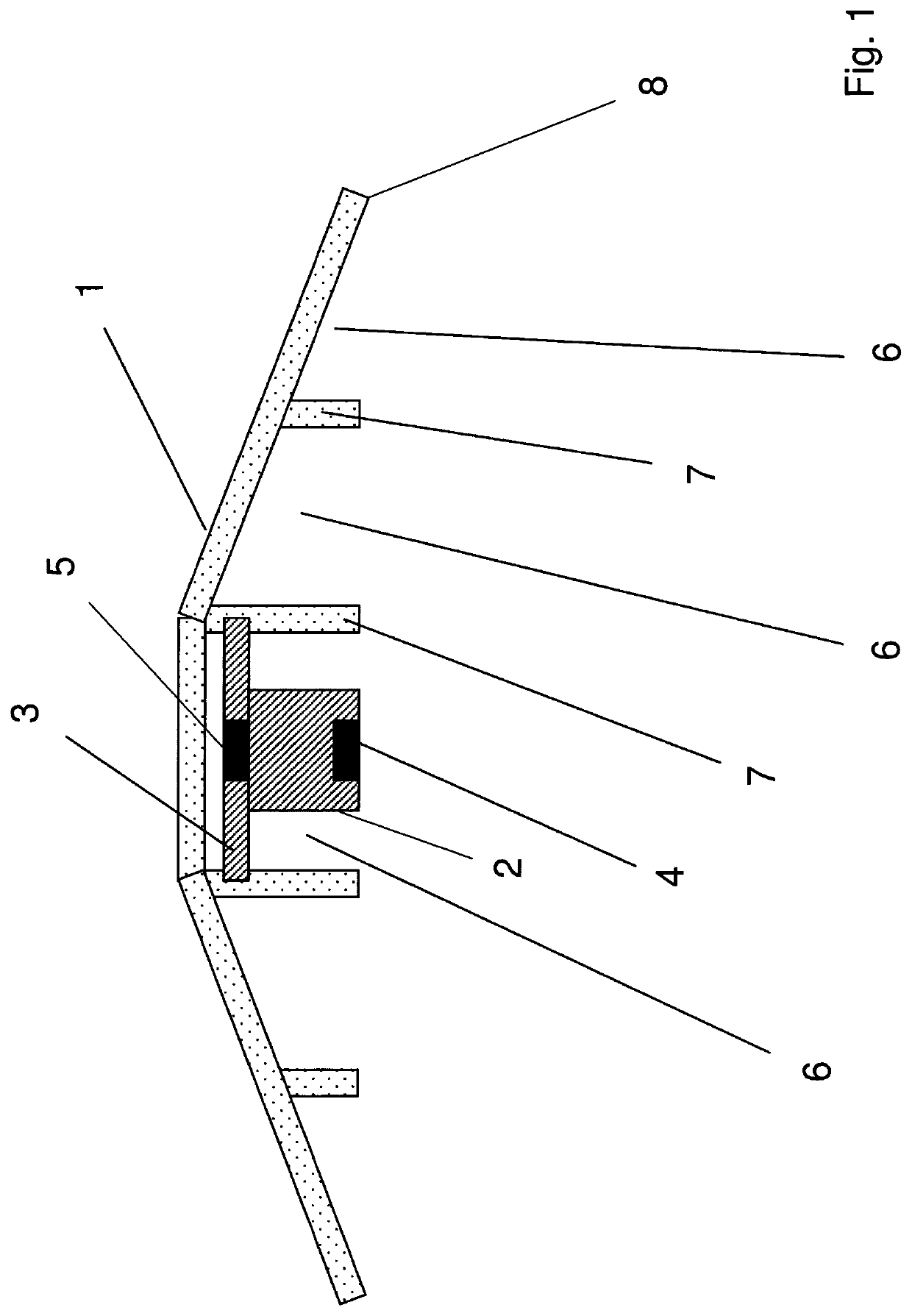
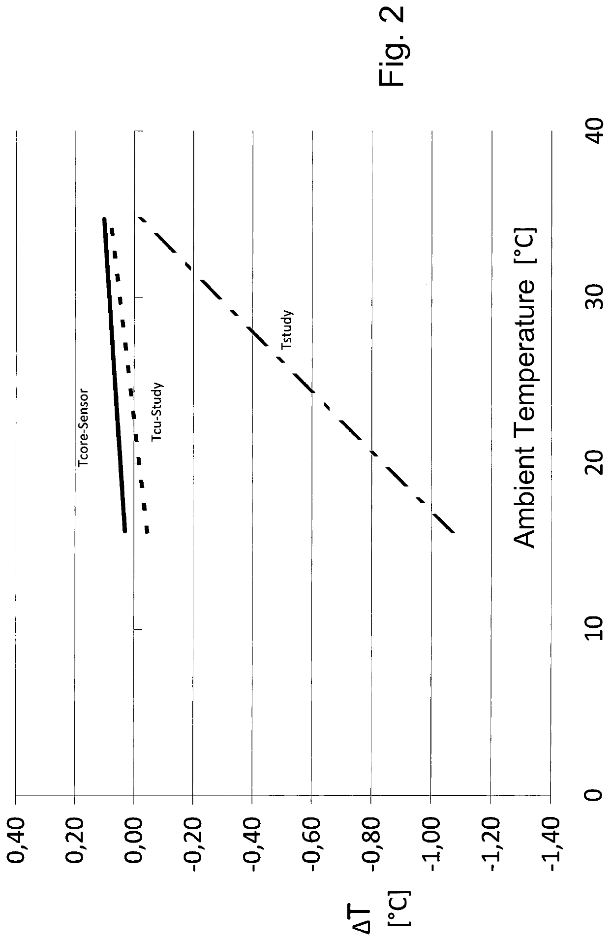
[0008]According to the present invention, the sensor block is held in a hood-shaped housing shell, which is shaped such that the first temperature sensor intended to come into contact with the skin surface and the outer edge of the housing shell, which edge extends peripherally at a spaced location therefrom, lie in one plane, so that the sensor block is surrounded by an air-filled cavity closed off by the housing shell when the housing shell is lying on the skin surface. The sensor block is preferably held centrally in the hood-shaped housing shell. It was found that a housing shell, which surrounds the sensor block in a hemisphere and is in contact with the skin surface with its outer peripheral edge at a spaced location from the sensor block, creates an insulating, air-filled cavity, which reduces an interfering, transversely directed heat flow in the sensor block far better than do all prior-art housing structures for dual temperature sensors, so that the error of measurement still caused thereby is absolutely negligible. It will be shown below in connection with the exemplary embodiment that the coefficient of heat transmission is reduced by a factor of more than 2 in a dual temperature sensor according to the present invention compared to a dual temperature sensor whose sensor block is insulated by a surrounding foam. The residual error of measurement that is still left thereafter due to transversely directed heat flow directed laterally from the sensor block is negligible, so that it is also no longer necessary to perform any corrections by calculation.
[0011]In an advantageous embodiment, the height of the web or webs is selected to be such that the edges of the webs facing away from the inner wall of the housing shell lie in the plane of the outer peripheral edge of the housing shell. The subjacent edges of the webs thus likewise lie on the skin surface when the housing shell is in contact with the skin surface, which contributes to the stabilization of the position of the dual temperature sensor in contact with the skin. Further, the lower edges of the webs, just like the outer peripheral edge of the housing shell, may be provided with adhesive elements, so that the dual temperature sensor can thus be held adheringly on the skin surface. It is also possible, in principle, that one or more such webs form a continuous wall in the interior of the housing shell, so that the inner cavity of the housing shell is divided into partial volumes.
[0013]In a preferred embodiment, the sensor block is held in the housing shell by at least one fastening element, which is connected, on the one hand, to the sensor block on the side of the second temperature sensor and, on the other hand, is connected directly or indirectly to the inner wall of the housing shell in the central area of the latter. As a result, the heat flow caused by the fastening of the sensor block through the fastening element is not critical, because the heat flow to the second temperature sensor is not practically affected thereby. Two or more thin carriers, which are connected in the central area of the housing shell to the inner wall of said housing shell or to one or more of the webs, may be formed, for example, at the upper end of the sensor block facing away from the skin Such a suspension of the sensor block in the housing shell minimizes any interfering heat flow through the suspension elements.
[0014]Another critical point concerning interfering heat flows is linked with the electric line, which connects the first temperature sensor on the skin surface to the analysis unit. Since materials having good electrical conductivity also have, as a rule, good thermal conductivity, there is a problem in that the line leading to the first temperature sensor, which also reaches into the outer space of the housing shall and the analysis unit, brings about an interfering heat flow from the first temperature sensor, because the temperature outside the housing shell is usually lower than the temperature of the skin surface, so that heat can flow off from the first temperature sensor. To circumvent this problem, the line connected to the first temperature sensor is led in the housing shell such that it is in heat-conducting contact with the skin surface during the operation when the housing shell is in contact with the skin surface. Over this path, in heat-conducting contact within the housing shell, the line has an at least partially non-straight or curved course from the first temperature sensor to the outside to the outer peripheral edge of the housing shell, at which the electric line is led out of the housing shell. Consequently, the line is not led directly in the radial direction to the outside to the outer edge of the housing shell and is not led out of the outer edge of the housing shell there, but the line has an at least partially curved or zigzag-like course, so that the length of the line, which is in heat-conducting contact with the skin surface, is increased compared to a direct lead-out from the housing shell. Such a large buffer section is created by this increased line length, which is in heat-conducting contact with the skin surface and is located between the lead-out of the line from the housing shell and the first temperature sensor, that no noticeable heat flow develops at the first temperature sensor within typical measurement times. A heat flow, which takes place through the line, which connects the first temperature sensor to the analysis unit, can be minimized in this way.
[0015]The electric line originating from the first temperature sensor may have, for example, at first a radial course up to the vicinity of the outer peripheral edge of the housing shell for this purpose. The line may be led, for example, in the course at a lower edge of a web. Following this, the line may extend peripherally at the outer edge in the interior of the housing shell, in which case it may be led at the peripheral outer edge, extending, for example, over 180°, i.e., over half the peripheral outer edge, before it is led out of the housing shell. It can be achieved in this way that there will be a sufficient electric line length in heat-conducting contact with the skin surface, so that temperature variations will have no noticeable effect on the measurement. As an alternative, a short line may also be led directly to the sensor if the cable consists, for example, of nickel, which has a low electric resistance but low heat conduction.

Problems solved by technology

It was found that a housing shell, which surrounds the sensor block in a hemisphere and is in contact with the skin surface with its outer peripheral edge at a spaced location from the sensor block, creates an insulating, air-filled cavity, which reduces an interfering, transversely directed heat flow in the sensor block far better than do all prior-art housing structures for dual temperature sensors, so that the error of measurement still caused thereby is absolutely negligible.

Method used


Image

  • Body core temperature sensor
  • Body core temperature sensor

Examples


Embodiment Construction

[0020]The dual temperature sensor shown in FIG. 1 has a sensor block 2, which carries a first temperature sensor 4 on a side facing the skin surface and a second temperature sensor 5 at the opposite end facing away from the skin. The sensor block 2 is shielded in a hemisphere by a hood-shaped housing shell 1. The housing shell 1 is shaped such that an outer peripheral edge 8 of the hood-shaped housing shell 1 lies in a same plane as the lower edge surface first temperature sensor 4, so that the housing shell forms a closed, air-filled cavity 6 around the sensor block 2 when the dual temperature sensor is in contact with the skin surface. One or more webs 7, originating from the inner wall of the housing shell, which impart a greater rigidity to the housing shell, may be provided in the interior of the housing shell 1. A height of the webs 7 may be dimensioned such that lower edges of the webs 7 likewise lie in the plane defined by the outer peripheral edge 8 of the housing shell and...


PUM

PropertyMeasurementUnit
path lengthaaaaaaaaaa
diameteraaaaaaaaaa
diameteraaaaaaaaaa

Abstract

A double temperature sensor determines the body core temperature of a living being. The double temperature sensor includes a sensor block (2), which on one side carries a first temperature sensor (4) provided for placing on the skin surface and on the other side carries a second temperature sensor (5) spaced from the first. An evaluating unit calculates the body core temperature using the measured values of the first and second temperature sensors. The sensor block (2) is held in a hood-shaped housing shell (1) which is shaped in such a manner that the first temperature sensor (4) on the sensor block and the peripheral outer edge (8) of the housing shell (1) spaced therefrom lie in one plane. When the housing shell (1) is lying on the skin surface, the sensor block (2) is surrounded by an air-filled cavity closed off by the housing shell.

Description

CROSS REFERENCE TO RELATED APPLICATIONS[0001]This application is a United States National Phase Application of International Application PCT / EP2014 / 000703 filed Mar. 14, 2014 and claims the benefit of priority under 35 U.S.C. § 119 of German Patent Application 10 2013 005 900.3 filed Apr. 5, 2013, the entire contents of which are incorporated herein by reference.FIELD OF THE INVENTION[0002]The present invention pertains to a dual temperature sensor for determining the body core temperature of a living being with a sensor block, which carries a first temperature sensor intended for being placed on the skin surface on one side and a second temperature sensor located at a spaced location from the first one on the other side, and with an analysis unit, which is set up to calculate the body core temperature using the measured values of the first and second temperature sensors.BACKGROUND OF THE INVENTION[0003]Such a dual temperature sensor measures the temperature on the skin surface with...

Claims


Application Information

Patent Timeline
Patent Type & Authority Patents(United States)
IPC IPC(8): A61B5/01G01K1/16G01K13/20A61B5/00
CPCA61B5/01A61B5/6801A61B5/7278G01K1/165G01K13/20A61B2560/0406A61B2562/04
Inventor KOCH, JOCHIMGRASSL, THOMAS
Owner DRAGERWERK AG
Learn More