Reaction chamber for a chemical reactor, and chemical reactor constructed therefrom

a chemical reactor and reaction chamber technology, applied in chemical/physical/physical-chemical stationary reactors, chemical apparatus and processes, chemical/physical/physical-chemical processes, etc., can solve the problems of increasing the pressure drop in the apparatus, the risk of fouling and blocking due to the small channel diameter of the process, and the inability to meet the needs of the process

Active Publication Date: 2021-06-15
SUZHOU SKYWELL HEALTHCARE INFORMATION CO LTD
View PDF10 Cites 0 Cited by
  • Summary
  • Abstract
  • Description
  • Claims
  • Application Information

AI Technical Summary

Benefits of technology

The present invention provides an apparatus that combines the requirements of high-speed mixing and efficient heat exchange. This is achieved through the use of specific heat-exchange surfaces and additional internal baffles to prevent co-rotation and support intensive mixing. The apparatus can be easily adapted to different material systems, and a decreased backmixing between the contents of the reaction chamber can be ensured through the use of a sleeve that projects out of the reaction chamber. In a further embodiment, the heating or cooling of the reaction chamber can be achieved through a continuous-flow heating or cooling medium, with a high specific heat-transfer surface area.

Problems solved by technology

On account of the low volume thereof, however, they are not suitable for reactions having a long residence time if a certain throughput is to be achieved.
In addition, the risk of fouling and blocking due to solids present in the process on account of the small channel diameter is a great challenge.
However, in this case the pressure drop in the apparatus increases and the discharge of solids is no longer possible, and so this measure is frequently unsuitable for practical use.
The achievable degree of backmixing in such apparatuses is frequently too high for applications that require a very narrow residence time distribution; in particular, if the reactor volume is low (some liters or less) and the implementable number of stages is therefore restricted.
However, such an apparatus has the disadvantage that an additional movable part and, in association therewith, a seal also, needs to be provided at each chamber.

Method used


Image

  • Reaction chamber for a chemical reactor, and chemical reactor constructed therefrom
  • Reaction chamber for a chemical reactor, and chemical reactor constructed therefrom
  • Reaction chamber for a chemical reactor, and chemical reactor constructed therefrom

Examples


Embodiment Construction

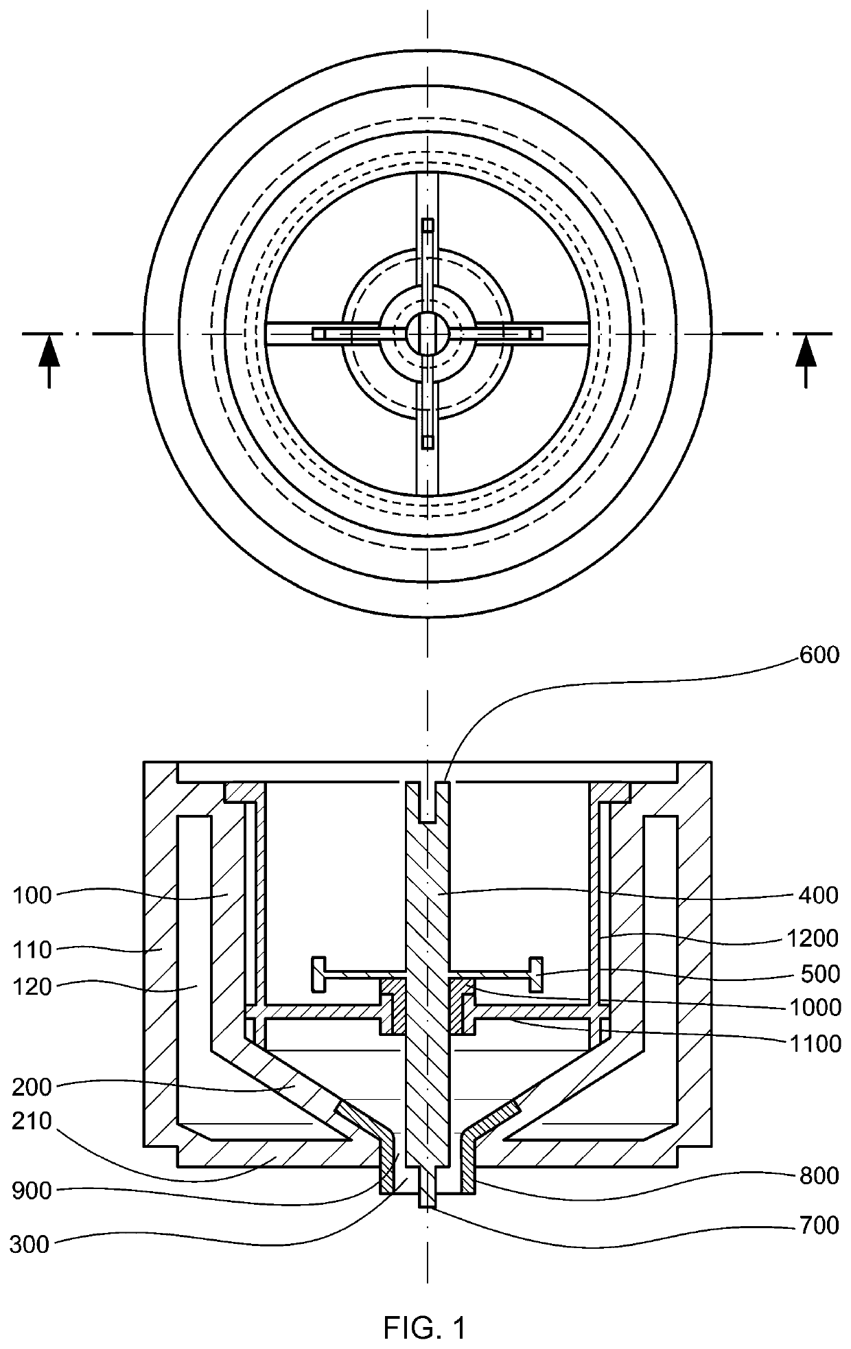
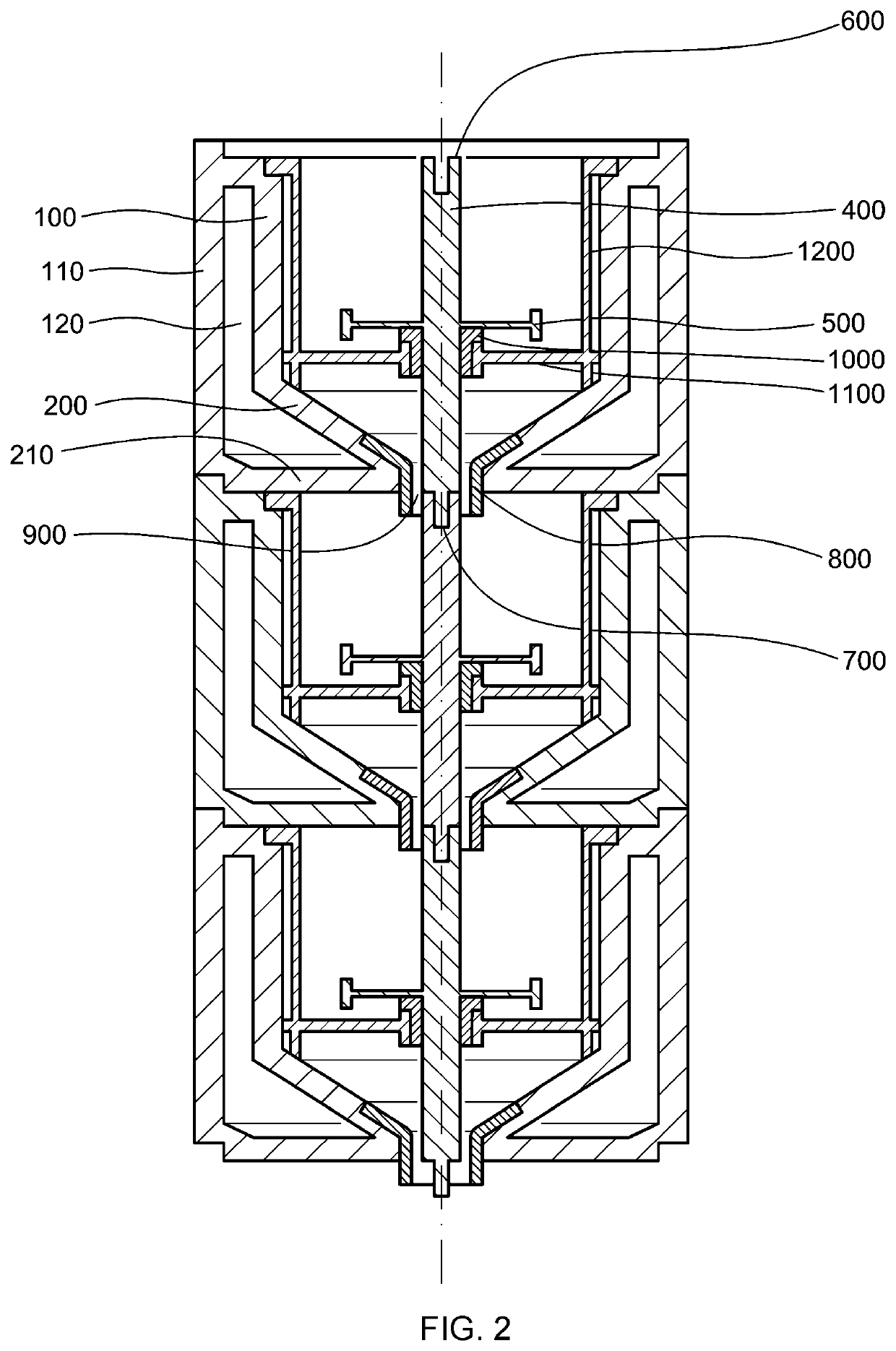
[0019]By means of a multiplicity of reaction chambers according to the invention, a chemical reactor can be built up in a modular manner and be flexibly adapted to changing requirements. The reaction chamber according to the invention can of course be used not only for chemical reactions in the narrow sense, but also for example for extractions and the like.

[0020]The “casing of the reaction chamber” is that part of the reactor chamber which, in the case of a vertical reaction chamber, is the lateral boundary of the chamber interior to the outside world. In the case of a cylindrical or cylinder-like reaction chamber, it is then the cylinder casing. Accordingly, the “floor of the reaction chamber” is the lower boundary, seen in the vertical direction, of the chamber interior to the outside world.

[0021]Following the concept of modular usability, in the reaction chamber there is already one agitator shaft having at least one agitator element, connected thereto, to agitate the contents o...


PUM


Abstract

A reaction chamber for a chemical reactor comprises a casing (100) of the reaction chamber, a floor (200) of the reaction chamber having an opening (300) located in the floor, an agitator shaft (400) located in the chamber and having at least one agitator element (500), connected thereto, wherein the agitator shaft (400), seen in the longitudinal direction, has a beginning (600) and an end (700). In the opening (300) of the floor (200) a removable sleeve (800) is provided, which projects out of the reaction chamber. The sleeve (800) is arranged in alignment with the axis of rotation of the agitator shaft (400). The internal diameter of the sleeve (800) is greater than the diameter of the agitator shaft (400) and the agitator shaft (400), at the beginning (600) thereof and / or at the end (700) thereof, is adapted to absorb reversibly a torque provided by means of a further shaft and / or to transmit a torque to a further shaft. Using such a reaction chamber, it is possible to build up modular chemical reactors having decreased backmixing.

Description

CROSS REFERENCE TO RELATED APPLICATIONS[0001]This application is a Divisional Application of U.S. patent application Ser. No. 15 / 318,924, filed Dec. 14, 2016, which is a § 371 National Stage Application of PCT / EP2015 / 063266, filed Jun. 15, 2015, which claims priority to German Application No. 10 2014 108 407.1 filed Jun. 16, 2014. Each of these applications is incorporated by reference in its entirety.BACKGROUND OF THE INVENTIONField of the Invention[0002]The work which led to this invention was funded in accordance with the grant agreement No. 246461 in the course of the seventh framework program of the European Union (FP7 / 2007-2013).Description of Related Art[0003]The present invention relates to a reaction chamber for a chemical reactor, comprising a casing of the reaction chamber, a floor of the reaction chamber having an opening located in the floor and an agitator shaft located in the chamber and having at least one agitator element, connected thereto. The invention further re...

Claims


Application Information

Patent Timeline
Patent Type & Authority Patents(United States)
IPC IPC(8): B01J19/18B01J19/00B01J19/20
CPCB01J19/1818B01J19/0066B01J19/1862B01J19/20B01J2219/0002B01J2219/0004B01J2219/00033B01J2219/00094B01J2219/00166B01J2219/00247B01J2219/185B01J2219/1943B01J2219/1946B01J19/0013
Inventor MLECZKO, LESLAWBUCHHOLZ, SIGURDBOOS, KARL-ROBERTFALSS, SEBASTIAN
Owner SUZHOU SKYWELL HEALTHCARE INFORMATION CO LTD
Why Eureka
Try Eureka