Apparatus for supporting substrate having gas supply hole and method of manufacturing same

a technology of apparatus and substrate, which is applied in the direction of electrical apparatus, electrostatic holding devices, electrical discharge tubes, etc., can solve the problems of reducing the diameter of the hole below a predetermined diameter, damage to the substrate support apparatus, and electrical discharge in the cooling gas supply hole, so as to minimize the occurrence of electrical discharge and reduce the diameter of the hole.

Active Publication Date: 2021-05-18
SEMES CO LTD
View PDF9 Cites 3 Cited by
  • Summary
  • Abstract
  • Description
  • Claims
  • Application Information

AI Technical Summary

Benefits of technology

[0011]Accordingly, the present invention has been made keeping in mind the above problems occurring in the related art, and an objective of the present invention is to provide an apparatus for supporting a substrate and a method of manufacturing the same, whereby occurrence of electrical discharge in a gas supply hole is minimized.
[0022]According to the exemplary embodiments of the present invention, forming of a gas supply hole is performed before sintering of a ceramic electrostatic chuck so as to allow the gas supply hole to be contracted during sintering of the ceramic electrostatic chuck, thus realizing a gas supply hole having a minimized diameter. This therefore provides an effect of minimizing occurrence of electrical discharge in the gas supply hole.

Problems solved by technology

This may lead to a serious problem of electrical discharge in the cooling gas supply holes.
Such electrical discharge may cause damage to the substrate support apparatus.
However, due to limitations of machining, there is a limit to reducing the diameter of the holes below a predetermined diameter (e.g., 0.1 mm).
In addition, sufficient insulation breakdown voltage may not be obtained only by providing a porous body of ceramic in a gas introduction passage.

Method used


Image

  • Apparatus for supporting substrate having gas supply hole and method of manufacturing same
  • Apparatus for supporting substrate having gas supply hole and method of manufacturing same
  • Apparatus for supporting substrate having gas supply hole and method of manufacturing same

Examples


first embodiment

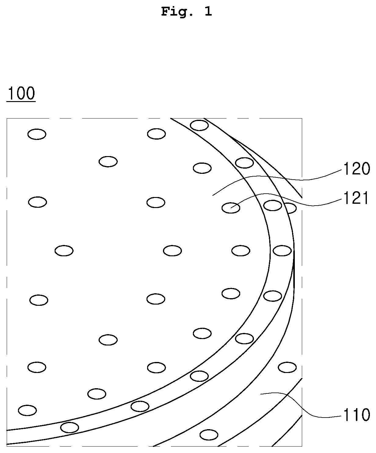
[0035]FIGS. 1 and 2 show an apparatus for supporting a substrate according to the present invention.

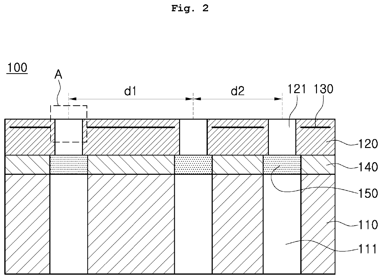
[0036]Referring to FIGS. 1 and 2, an apparatus for supporting a substrate according to an embodiment includes a base plate 110, and a ceramic electrostatic chuck 120.

[0037]The base plate 110 supports the ceramic electrostatic chuck 120. The base plate 110 has an upper surface and a lower surface, and the ceramic electrostatic chuck 120 is disposed on the upper surface of the base plate 110. The base plate 110 may be made of a metal material, for example, aluminum.

[0038]The base plate 110 includes at least one first gas supply hole 111 formed therein. The at least one first gas supply hole 111 is formed to penetrate the upper and lower surfaces of the base plate 110.

[0039]This configuration allows the base plate 110 to serve to control the temperature of the electrostatic chuck 120. For example, when the electrostatic chuck 120 is needed to be cooled, a cooling medium may be introduced...

second embodiment

[0059]FIGS. 6 and 7 show an apparatus for supporting a substrate according to the present invention.

[0060]Referring to FIGS. 6 and 7, an apparatus for supporting a substrate according to a second embodiment includes a base plate 110 and an electrostatic chuck 120.

[0061]The base plate 110 includes at least one first gas supply hole 111 formed therein. The at least one first gas supply hole 111 is formed to penetrate upper and lower surfaces of the base plate 110.

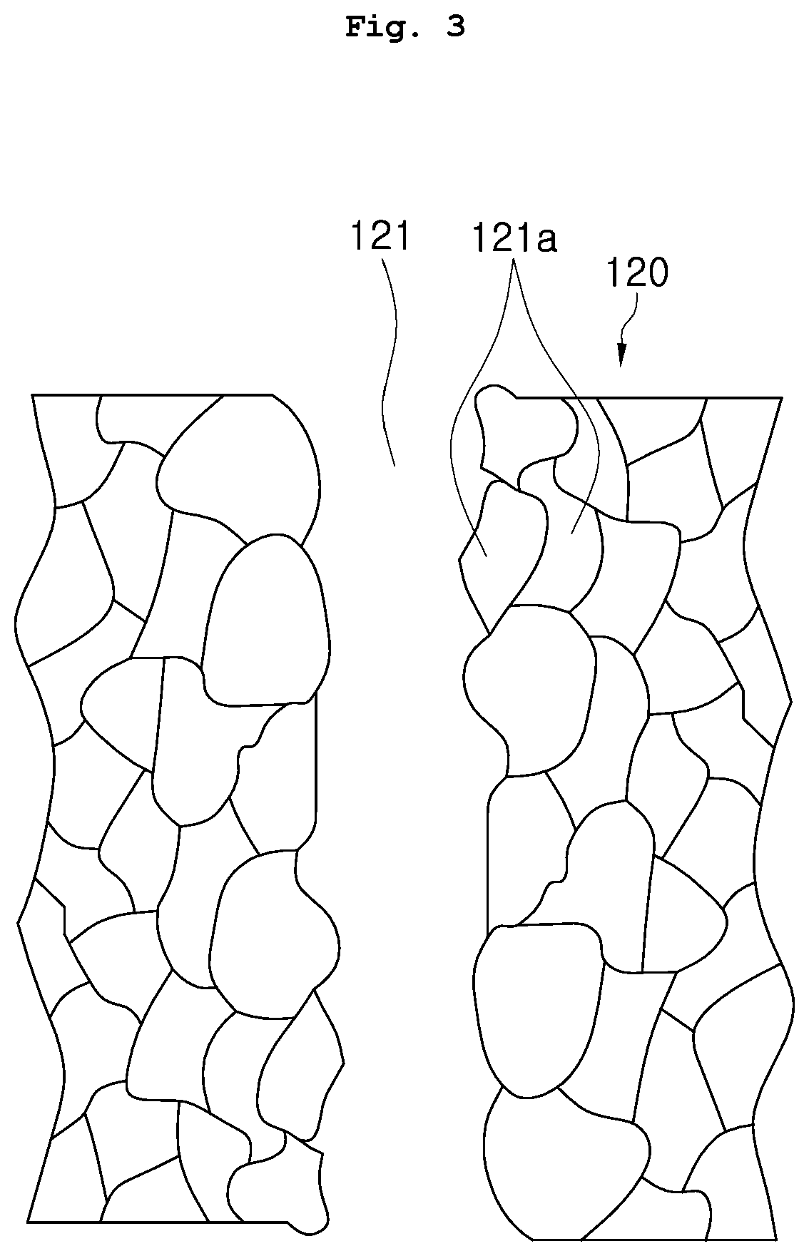
[0062]The electrostatic chuck 120 is disposed on the upper side of the base plate 110. The electrostatic chuck 120 is bonded and fixed onto the base plate 110 by an adhesive layer 140 interposed therebetween. The electrostatic chuck 120 includes at least one second gas supply hole 122 formed therein. The at least one second gas supply hole 122 is formed to penetrate upper and lower surfaces of the electrostatic chuck 120.

[0063]The second gas supply holes 122 may be grouped into a plurality of groups of second gas supply holes...


PUM


Abstract

An apparatus for supporting a substrate is proposed. The apparatus includes: a base plate including at least one first gas supply hole formed therein so as to allow supply of a temperature control gas; and an electrostatic chuck provided on the base plate to support the substrate, and including at least one second gas supply hole formed therein so as to be in communication with the at least one first gas supply hole, wherein the at least one second gas supply hole is formed before sintering of the electrostatic chuck.

Description

CROSS REFERENCE TO RELATED APPLICATION[0001]The present application claims priority to Korean Patent Application No. 10-2018-0122794, filed Oct. 15, 2018, the entire contents of which is incorporated herein for all purposes by this reference.BACKGROUND OF THE INVENTIONField of the Invention[0002]The present invention relates to an apparatus for supporting a substrate, the apparatus being used during processing of a semiconductor substrate such as a wafer, and a method of manufacturing the same.Description of the Related Art[0003]Recently, plasma processing equipment has been widely used to produce thin film deposition and etching on a semiconductor substrate in the process of fabricating a semiconductor device.[0004]One example of plasma processing equipment includes a processing chamber having a space for processing a semiconductor substrate, and a substrate support apparatus disposed inside the processing chamber to support the semiconductor substrate.[0005]One example of the subs...

Claims


Application Information

Patent Timeline
Patent Type & Authority Patents(United States)
IPC IPC(8): H01T23/00H01L21/683
CPCH01L21/6833H01J37/32715H01J37/32724H01L21/67109H01L21/6831H01L21/68757H01L21/67017H01L21/67248H02N13/00H01L21/02
Inventor LEE, SANG KEELEE, JAE KYUNG
Owner SEMES CO LTD
Why Eureka
Try Eureka