
Data obtaining method, inverter, and rotating electric machine

a technology of inverters and electric machines, applied in the direction of electric motor control, electric commutators, control systems, etc., can solve the problems of significant damage, suspension of production lines or entire plants, and suspension of facilities

Active Publication Date: 2021-05-11
HITACHI IND EQUIP SYST CO LTD
View PDF8 Cites 0 Cited by
  • Summary
  • Abstract
  • Description
  • Claims
  • Application Information

AI Technical Summary

Benefits of technology

Enables effective sign monitoring of electromechanical systems with a reduced equipment configuration, capable of detecting abnormalities in rotating electric machines without the need for additional sensors or dedicated analyzers.

Problems solved by technology

For example, a rolling mill in a steel plant, etc. as a machine device driven using a rotating electric machine may cause suspension of an operation of a production line or the entire plant when the rolling mill stops due to a failure.
Suspension of a facility due to occurrence of accidental abnormality is significantly damaging.

Method used


Image

  • Data obtaining method, inverter, and rotating electric machine
  • Data obtaining method, inverter, and rotating electric machine
  • Data obtaining method, inverter, and rotating electric machine

Examples


embodiment

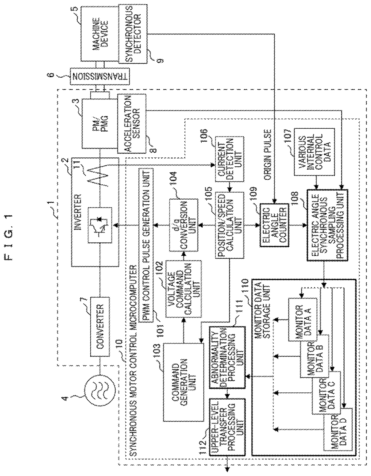
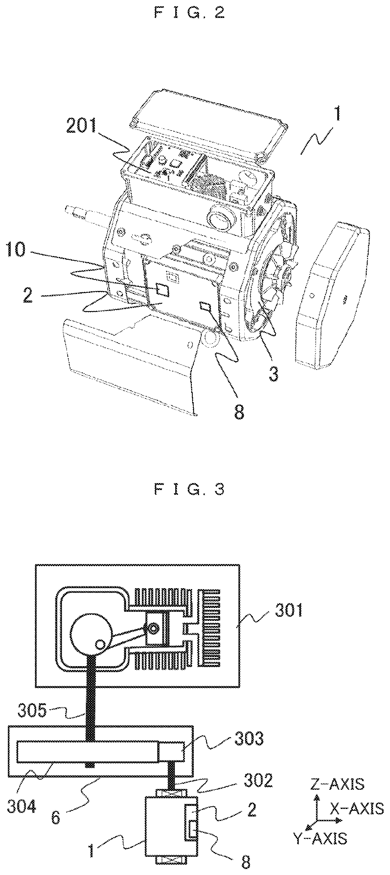
[0023]FIG. 1 is a configuration block of an electromechanical system using a rotating electric machine in the present embodiment. Incidentally, hereinafter, the rotating electric machine is referred to as a rotating electric machine assembly. In addition, in FIG. 1, a part enclosed with a broken line is the rotating electric machine assembly 1, and an external appearance thereof is illustrated in FIG. 2. In FIG. 2, the rotating electric machine assembly 1 includes a permanent magnet type synchronous electric motor 3 and an inverter 2 for driving the synchronous electric motor therein. The inverter 2 is equipped with a synchronous motor control microcomputer 10 and an acceleration sensor 8 which are control devices for the synchronous electric motor. Normally, these components are fixed by a filler, etc. so as to be directly fixed to the permanent magnet type synchronous electric motor 3 which is a mechanical component, and consideration is given to avoid unnecessary resonance caused...


PUM


Abstract

Provided are a data obtaining method, an inverter, and a rotating electric machine capable of managing the operation state of a device without complicating the configuration thereof. Therefore, the data obtaining method uses an inverter for controlling a synchronous electric motor, wherein a position / speed calculation unit of the inverter calculates an electric angle of the synchronous electric motor from the value of the current flowing between the synchronous electric motor and the inverter and obtains data for each electric angle by sampling internal data within the inverter, said internal data being used for controlling the synchronous electric motor in synchronization with the information of the electric angle.

Description

TECHNICAL FIELD[0001]The present invention relates to a data obtaining method, an inverter, and a rotating electric machine, and particularly relates to abnormality detection of a machine device, which performs a periodic operation, driven using the rotating electric machine.BACKGROUND ART[0002]For example, a rolling mill in a steel plant, etc. as a machine device driven using a rotating electric machine may cause suspension of an operation of a production line or the entire plant when the rolling mill stops due to a failure. Suspension of a facility due to occurrence of accidental abnormality is significantly damaging. For this reason, it is necessary to detect an abnormality and perform preventive maintenance before a failure leading to facility suspension occurs, and there are various technologies for detecting an abnormality before a failure occurs.[0003]In general, to detect a state of a target machine device in detail, various sensors are attached, and data obtained therefrom ...

Claims


Application Information

Patent Timeline
Patent Type & Authority Patents(United States)
IPC IPC(8): H02P6/14H02P27/08
CPCH02P27/085H02P27/06H02P6/18H02P25/022H02P21/0025H02P23/14H02P27/08H02P21/18H02M7/5395G01R31/34H02P2207/05H02M1/0009
Inventor TOMITA, TOSHIOSAITO, KENICHIIWASE, YUUTASANO, MASAHIRO
Owner HITACHI IND EQUIP SYST CO LTD
Learn More