
Sound generation angular velocity-adjustable twirling device

a twirling device and angular velocity technology, applied in the direction of instruments, musical instruments, rattles, etc., can solve the problems of not permitting the colors of the sport teams to be readily shown or seen, cumbersome and tiring to twirl, and heavy weight of pennants associated with handles, etc., to achieve easy detachable fastening and firm grip

Active Publication Date: 2021-04-20
KRYSTIAN SANDS
View PDF1 Cites 0 Cited by
  • Summary
  • Abstract
  • Description
  • Claims
  • Application Information

AI Technical Summary

Benefits of technology

The twirling device is a fastening mechanism that can be attached to a fabric-article at either a central or peripheral point. It allows the fabric-article to spin at a speed dependent on its center of gravity, which is determined by varying the attachment point. The device can be used to unroll and twirl the fabric-article, and the point of attachment between the device and fabric-article affects the speed and type of twirling. The technical effects of this patent text are an inexpensive twirling device that can be easily attached to fabric-articles and rotate them at a controlled speed.

Problems solved by technology

However, pennants, flags, and rally towels are often cumbersome and tiring to twirl after a duration.
Pennants associated with handles are often cumbersome, heavy, and tiring to spin.
Additionally, while rotating the pennant, the pennant or towel often twists and curls onto itself, not permitting the colors of the sport teams to be readily shown or seen.
The problem with these spinning devices is that they do not enable the center of gravity of the pennant or flag to be changed, so as to create different unfurling and twirling effects.
Also, the handle used to control the device is not easy to hold when rotating.

Method used


Image

  • Sound generation angular velocity-adjustable twirling device
  • Sound generation angular velocity-adjustable twirling device
  • Sound generation angular velocity-adjustable twirling device

Examples


Embodiment Construction

[0062]The following detailed description is merely exemplary in nature and is not intended to limit the described embodiments or the application and uses of the described embodiments. As used herein, the word “exemplary” or “illustrative” means “serving as an example, instance, or illustration.” Any implementation described herein as “exemplary” or “illustrative” is not necessarily to be construed as preferred or advantageous over other implementations. All of the implementations described below are exemplary implementations provided to enable persons skilled in the art to make or use the embodiments of the disclosure and are not intended to limit the scope of the disclosure, which is defined by the claims. For purposes of description herein, the terms “upper,”“lower,”“left,”“rear,”“right,”“front,”“vertical,”“horizontal,” and derivatives thereof shall relate to the invention as oriented in FIG. 1. Furthermore, there is no intention to be bound by any expressed or implied theory pres...


PUM


Abstract

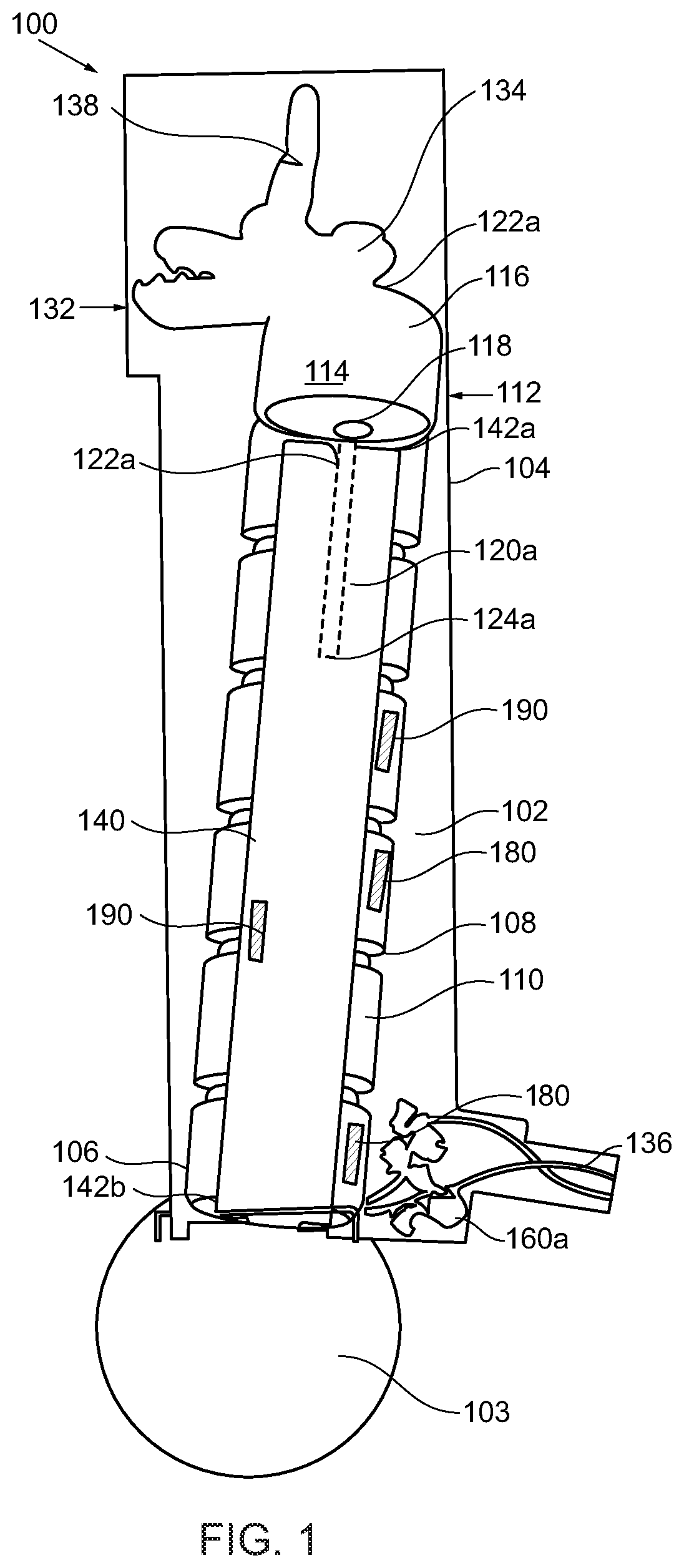
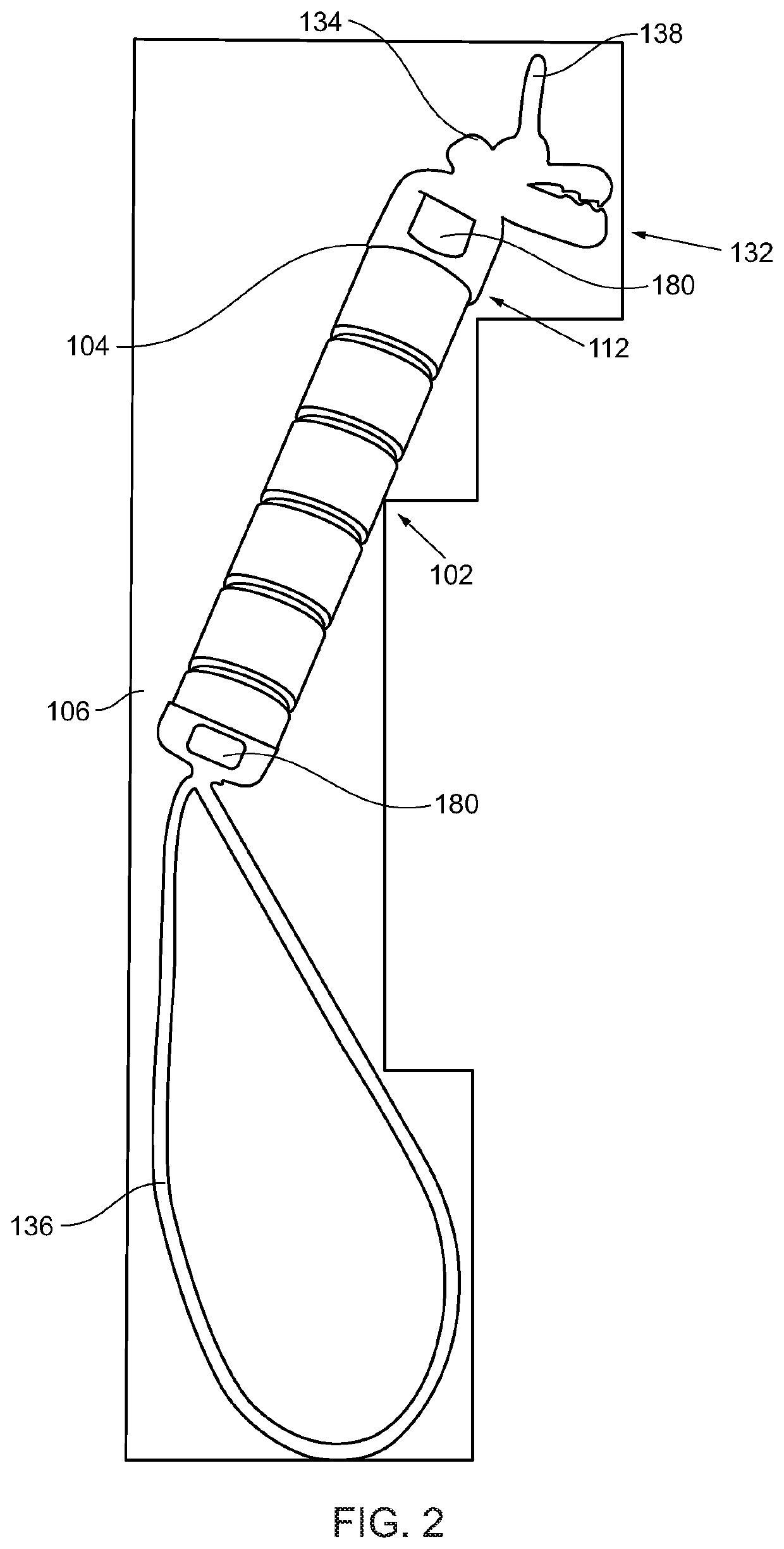
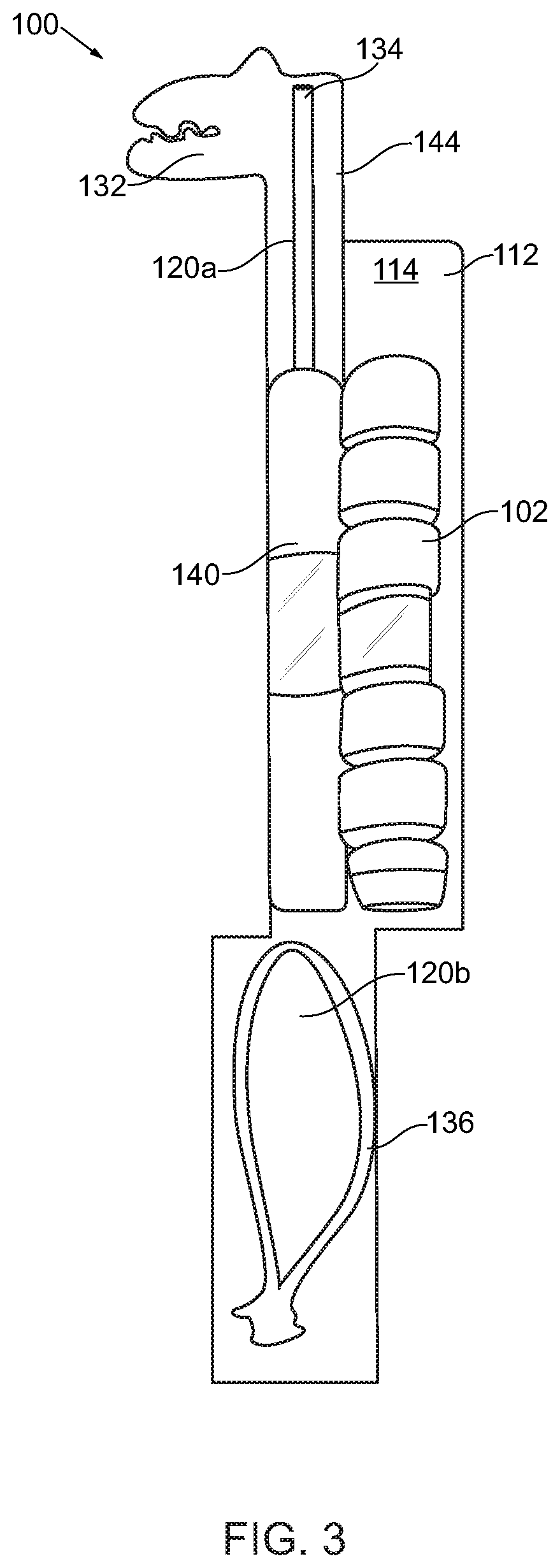
A sound generation angular velocity-adjustable twirling device detachably attaches to a fabric-article at a peripheral attachment point or a central attachment point and enables rotation of fabric-article. The fabric-article unfurls and twirls at a rate dependent on the center of gravity at different attachment points on fabric-article. A rod forms the central axis. A textured outer sleeve encapsulates the rod for secure grasping. A first axis positions in the outer sleeve, fixedly attaching to a first-rod end. A fastening mechanism rotates freely about the first axis while retaining the fabric-article. The rotating fastening mechanism and the stationary first axis form a rotational relationship with low friction coefficient. A second axis pins a strap to the second-rod end. The device generates sound while twirling through a gear assembly and / or percussion instruments. The sound generated is proportional to the angular velocity of the gear, and to the applied torque to the sleeve.

Description

FIELD OF THE INVENTION[0001]The present invention generally relates to a sound generation angular velocity-adjustable twirling device. More so, the present invention relates to a twirling device that twists and twirls a fabric-article at a rate that is dependent on the center of gravity formed by varying the attachment points on the fabric-article and also dependent on the user who holds the twirling device to apply a rotating force thereon; and further simultaneously generates sound while twirling through use of a gear assembly and / or at least one percussion instrument, such that the angular velocity of the twirling device is proportional to the sound pressure generated by the gear assembly, the percussion instrument, and the twirling fabric-article.BACKGROUND OF THE INVENTION[0002]The following background information may present examples of specific aspects of the prior art (e.g., without limitation, approaches, facts, or common wisdom) that, while expected to be helpful to furthe...

Claims


Application Information

Patent Timeline
IPC IPC(8): G10D13/01G10K3/00
CPCG10D13/01G10K3/00G10K1/071
Inventor SANDS, KRYSTIAN K. R.
Owner KRYSTIAN SANDS
Learn More