
Central bidirectional rotation locking mechanism for folding tent

a folding tent and locking mechanism technology, applied in tents/canopies, building types, constructions, etc., can solve the problems of direct influence on the overall complexity of the product structure, the difficulty the traditional locking method of unfolding and folding, so as to achieve convenient and fast operation and strengthen practicability.

Active Publication Date: 2021-04-20
ZHEJIANG JASAN LEISURE PROD
View PDF9 Cites 6 Cited by
  • Summary
  • Abstract
  • Description
  • Claims
  • Application Information

AI Technical Summary

Benefits of technology

[0009]A connection column is vertically disposed on an edge of the second lower plate, an arc-shaped travel hole that penetrates up and down is provided at a corresponding location on an edge of the unlocking plate, and after the connection column extends through the travel hole, the connection column is fixedly connected to the first lower plate by a fastening member. The setting may ensure rotation of the unlocking plate when the first lower plate and the second lower plate remain still.
[0013]A radian of the arc-shaped travel hole is the same as a radian of the unlocking plate. This setting facilitates smooth rotation of the unlocking plate.
[0015]The present invention has a properly designed structure. The locking mechanism can bidirectionally rotate by disposing a rotation mechanism. In addition, the unlocking plate is disposed, so that the lock rod can be unlocked provided that the unlocking plate is screwed. Operation is more convenient and quicker, and practicability is stronger.

Problems solved by technology

This component directly affects overall complexity of a product structure and difficulty of unfolding and folding, and also relate to production costs.
Although an existing lock member for a folding tent resolves a problem that a traditional lock member has a complex structure and is tedious is operate, an unfolding manner of the traditional lock is relatively limited, especially a rotatably unfolded lock member can only be unfolded in one direction, and is restrictively used.

Method used


Image

  • Central bidirectional rotation locking mechanism for folding tent
  • Central bidirectional rotation locking mechanism for folding tent
  • Central bidirectional rotation locking mechanism for folding tent

Examples


Embodiment Construction

[0032]The present invention is further described in detail below with reference to the accompanying drawings of the specification, and specific implementations are provided.

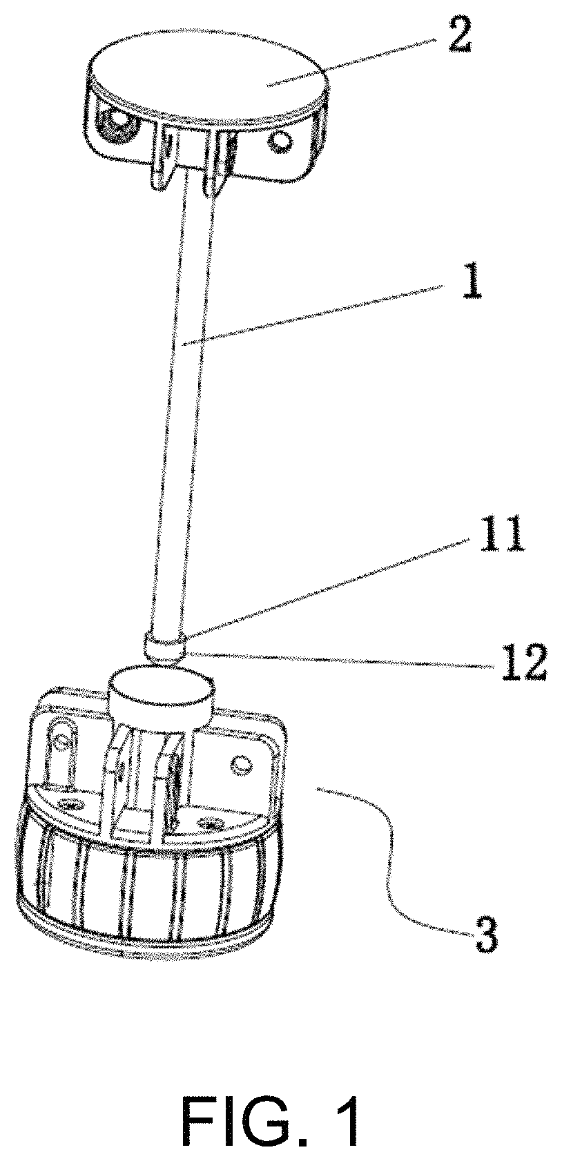
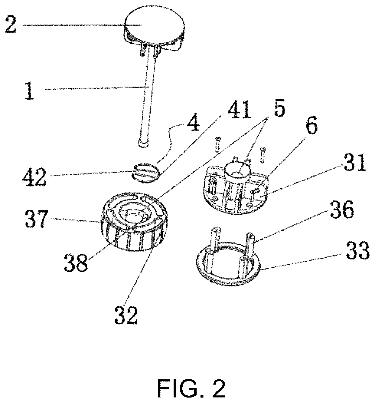
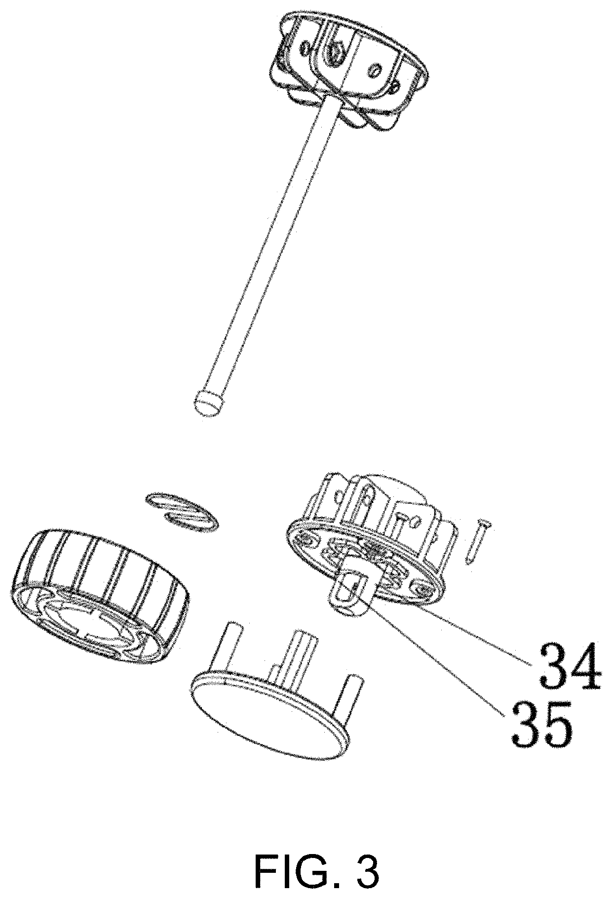
[0033]The present invention discloses a central bidirectional rotation locking mechanism for a folding tent. The locking mechanism is mainly used to unfold and fold the folding tent. A structure of the locking mechanism is shown in FIG. 1 to FIG. 11, and includes a lock rod 1, an upper lock plate 2 fixedly disposed at an upper end of the lock rod 1, and a lower lock plate assembly 3 detachably connected to a lower end of the lock rod 1. The lower lock plate assembly 3 sequentially includes a first lower plate 31, an unlocking plate 32, and a second lower plate 33 from top to bottom. The upper lock plate 2 is hingedly connected to a long tent bone and the first lower plate 31 is hingedly connected to a short tent bone. An elastic locking member 4 and an unlocking mechanism used to control the elastic locking membe...


PUM


Abstract

A central bidirectional rotation locking mechanism for a folding tent includes a lock rod, an upper lock plate, and a lower lock plate assembly. The lower lock plate assembly includes a first lower plate, an unlocking plate, and a second lower plate. An elastic locking member and an unlocking mechanism used to control the elastic locking member to perform locking are disposed in the unlocking plate. The elastic locking member is used to lock the lock rod, and the unlocking plate is capable of bidirectional rotation. When the unlocking plate rotates, the unlocking mechanism is enabled to unlock the elastic locking member and the lock rod.

Description

CROSS-REFERENCE TO RELATED APPLICATION[0001]This application claims the priority benefit of China application serial no. 201922364040.5, filed on Dec. 25, 2019. The entirety of the above-mentioned patent application is hereby incorporated by reference herein and made a part of this specification.BACKGROUNDTechnical Field[0002]The present invention belongs to the field of technologies of components of folding tents, and specifically, to a central bidirectional rotation locking mechanism for a folding tent.Description of Related Art[0003]With the development of the tent industry, folding tents are widely used, and a lock member that controls unfolding and folding of a folding tent has become a main research object for various manufacturers. This component directly affects overall complexity of a product structure and difficulty of unfolding and folding, and also relate to production costs. Although an existing lock member for a folding tent resolves a problem that a traditional lock m...

Claims


Application Information

Patent Timeline
Patent Type & Authority Patents(United States)
IPC IPC(8): E04H15/48
CPCE04H15/48E04H15/28E04H15/44E04H15/32E04H15/34
Inventor YING, QIWANGSUN, YUANRUHE, JIAN
Owner ZHEJIANG JASAN LEISURE PROD
Learn More