
Connector for two workpieces

a technology for connecting parts and workpieces, applied in the direction of nails, constructions, fastening means, etc., can solve the problems of occupying a large amount of force by protruding parts, and achieve the effect of convenient screwing in, improved fit, and reliable positioning for mounting on the workpi

Active Publication Date: 2021-04-06
KNAPP GMBH
View PDF12 Cites 0 Cited by
  • Summary
  • Abstract
  • Description
  • Claims
  • Application Information

AI Technical Summary

Benefits of technology

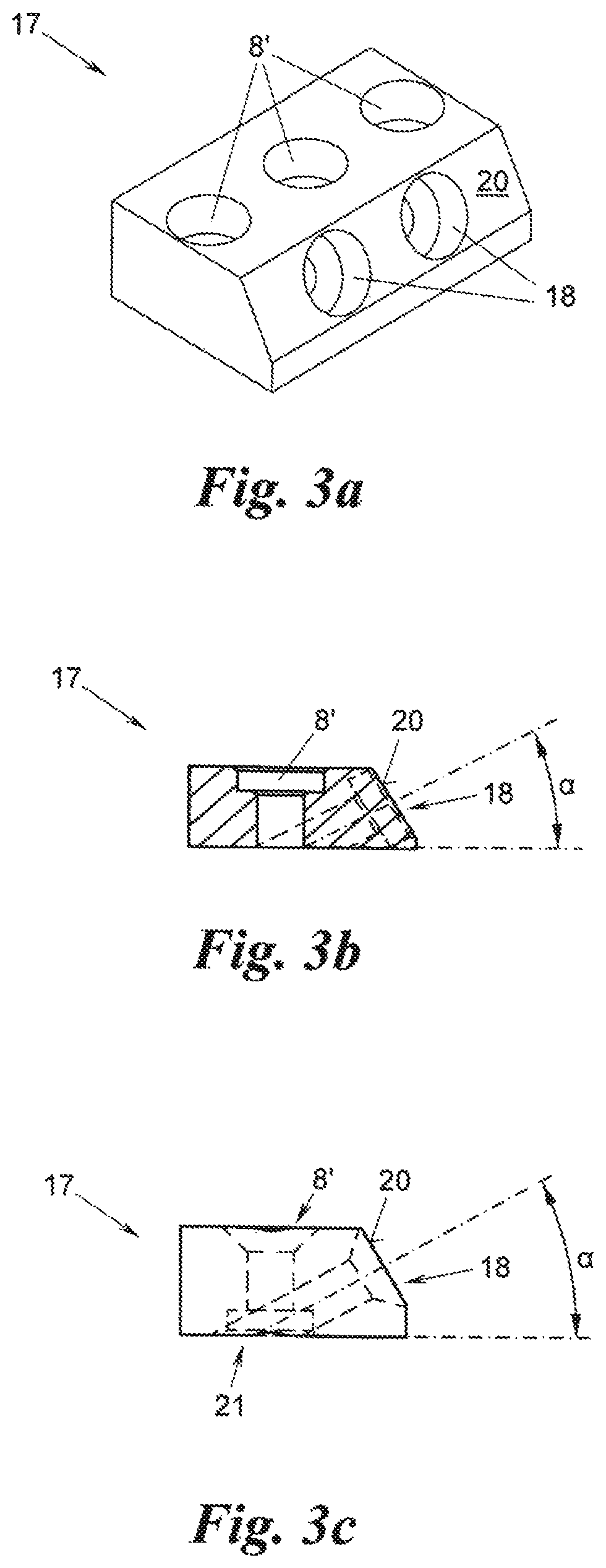
The disclosed invention aims to improve the connection between two fittings by enhancing its load-bearing capability, durability and overall size. The connector achieves this by supporting the forces acting on it through the edge of the fitting against the protrusion of the other fitting. The connector is designed to withstand greater forces with constant weight or size, while also being easily mounted on the workpiece. It reduces the impact loads, keeps the workpiece away from damage, and allows for a durable connection between the two fittings. The design features a protrusion with bores for screw mounting, a chamfered protrusion for easier screw insertion, and a V-shaped mouth for easy insertion of the projection into the slot. The two fittings may have different forms or be mirror-symmetrical to each other, simplifying the structure and handling of the connector.

Problems solved by technology

However, the protrusion may take up particularly high forces if it is formed integrally on the fitting or is welded thereto, as is preferred.

Method used


Image

  • Connector for two workpieces
  • Connector for two workpieces
  • Connector for two workpieces

Examples


Embodiment Construction

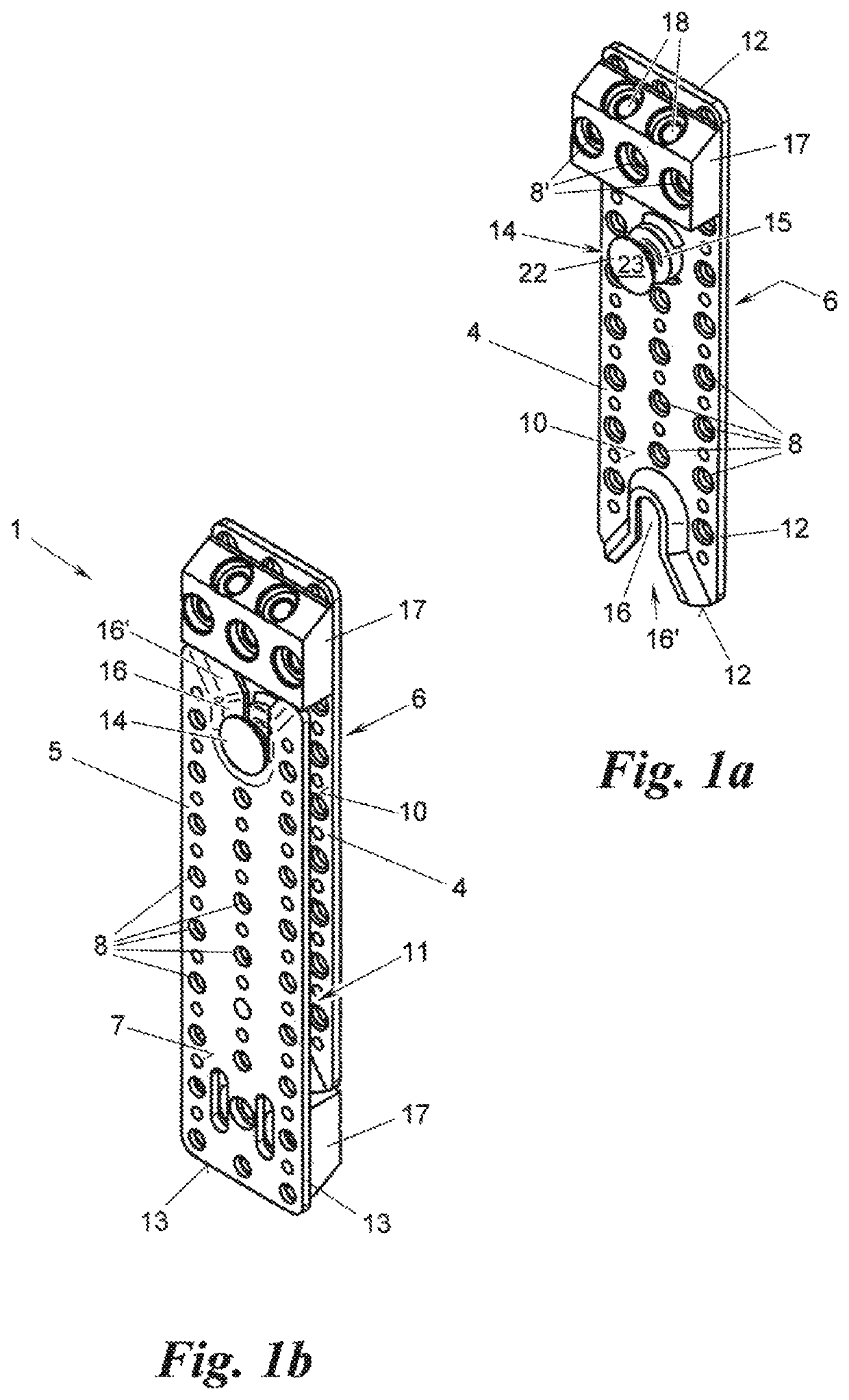
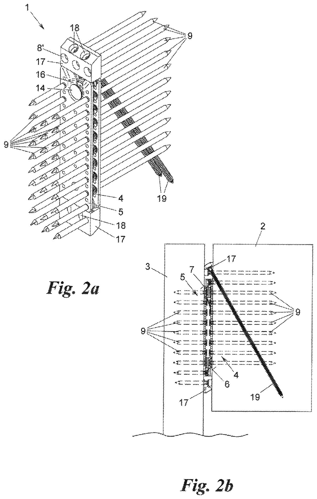
[0019]FIGS. 1a, 1b, 2a and 2b show examples for a connector 1 for two workpieces 2, 3 made of wood, in particular glued laminated timber, made of concrete, masonry, stone, metal or the like, for example beams and / or vertical components, for example pillars, posts or walls. The connector 1 has a first and a second fitting 4, 5. The first fitting 4 is mounted with one of its sides 6 on one of the workpieces 2, 3, and the second fitting 5 is mounted with its other side 7 on the other of the workpieces 2, 3. To this end, each of the fittings 4, 5 for example has bores 8 for screws 9, nails, pins or the like, which are anchored in the relevant workpiece 2, 3.

[0020]By means of its other side 10, the first fitting 4 is anchored on the other side 11 of the second fitting 5, and the two workpieces 2, 3 are in this way connected to one another. The two fittings 4, 5 have a circumferential edge 12, 13 between their one and other sides 6, 7, 10, 11 respectively.

[0021]In order to anchor the two ...


PUM


Abstract

The present disclosed subject matter relates to a connector for two workpieces, which are in particular made of wood. The connector comprises a first and a second fitting which may be mounted on one of the workpieces each by their one side and may be anchored to one another by their other sides, and which each have a circumferential edge between their one and other side. At least the first fitting has a projection with an undercut on its other side and the second fitting has a slot, starting from its edge and corresponding to the undercut, for anchoring the projection. At least one of the fittings has a protrusion on its other side and running transverse to the direction of the slot for resting of the edge of the other fitting when the projection is in the position anchored in the slot.

Description

CROSS-REFERENCE TO RELATED APPLICATIONS[0001]This application is a National Phase application of International Application No. PCT / EP2018 / 074561 filed Sep. 12, 2018, which claims priority to European Patent Application No. 17 191 575.4 filed Sep. 18, 2017, the disclosures of which are incorporated herein by reference.TECHNICAL FIELD[0002]This disclosed subject matter relates to a connector for two workpieces, which are in particular made of wood.BACKGROUND[0003]Connectors of this kind are known for example from DE102 27 661 B3 and EP1 856 417 B1 and are sold under the trademark RICON® S by the company Knapp GmbH, Euratsfeld, Austria. They are particularly suitable for the construction of connections capable of bearing heavy loads in the field of timber engineering, for example for the connection of main beams, secondary or cross beams, cross passes, trusses, pillars, posts, walls, or the like. The fittings are usually made of metal, for example high-strength aluminium, and the workp...

Claims


Application Information

Patent Timeline
Patent Type & Authority Patents(United States)
IPC IPC(8): E04B1/26E04B1/41E04B1/38
CPCE04B1/2604E04B1/40E04B2001/2628E04B2001/2644E04B2001/2652E04B2001/405E04B2001/2632F16B21/09F16B15/0053F16B5/07F16B12/26F16B12/14E04B1/388E04B2001/389
Inventor KNAPP, FRIEDRICH
Owner KNAPP GMBH
Learn More