Charger circuit and intelligent charging control method thereof

a charger circuit and intelligent charging technology, applied in the direction of safety/protection circuits, instruments, transportation and packaging, etc., can solve the problems of fire disasters, shortening the battery life, damage to the battery, etc., to prolong the battery life, avoid disasters, and prevent overcharging of batteries.

Active Publication Date: 2021-03-30
SHENZHEN LIANXUNFA TECH CO LTD
View PDF2 Cites 0 Cited by
  • Summary
  • Abstract
  • Description
  • Claims
  • Application Information

AI Technical Summary

Benefits of technology

[0003]To overcome the defects and drawbacks of the prior art, the invention provides a charger circuit and an intelligent charging control method thereof to prolong the service life of batteries of consumer electrical appliances by effectively avoiding overcharging of the batteries and to avoid disasters caused by overcharging of the batteries.
[0017]Step S40, intelligently judging whether or not the battery is fully charged by detecting a charging current and a charging voltage in the charging loop through the MCU in the charging process; if not, continuing to charge the battery and detecting the charging current and the charging voltage; or if yes, controlling the switching element to be turned off, so that the charging loop is cut off to end charging, and thus, overcharging of the battery is prevented.
[0020]By adoption of the invention, a charger is able to intelligently judge whether or not a to-be-charged electrical appliance is plugged into the charging interface, automatically charges the electrical appliance in a corresponding charging mode and effectively prevents overcharging of batteries of consumer electrical appliances, thus, prolonging the battery life and avoiding disasters caused by overcharging of the batteries.

Problems solved by technology

In actual life, chargers with USB interfaces are sometimes used as power sources of various electronic devices and are kept in the power-on state to supply power, which will result in the following drawbacks: the battery life may be shortened due to imperfect charging management, and batteries may be damaged or even catch fires due to overcharging, which will in turn result in fire disasters.

Method used


Image

  • Charger circuit and intelligent charging control method thereof
  • Charger circuit and intelligent charging control method thereof
  • Charger circuit and intelligent charging control method thereof

Examples


Embodiment Construction

[0026]The invention is further expounded below with the accompanying drawings and specific embodiments so that those skilled in this field can have a better understanding of the invention.

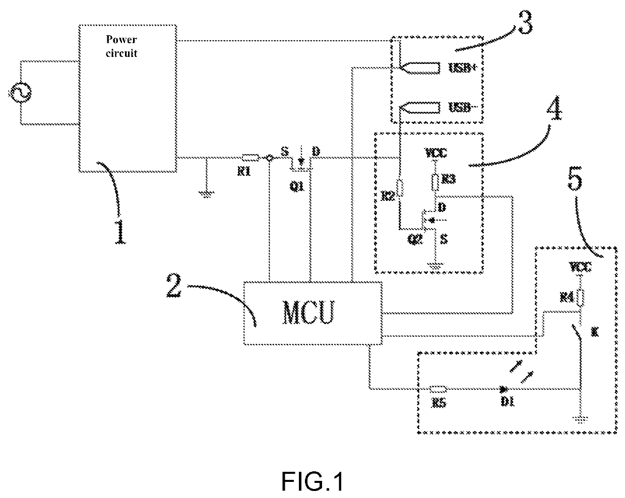
[0027]As shown in FIG. 1, the invention provides a charger circuit. The charger circuit comprises a power circuit 1 used to generate a charging voltage, a charging output switch, a MCU 2 and an electrical appliance plug-in detection circuit 4. A positive output terminal and a negative output terminal of the power circuit are respectively connected to a positive connecting terminal and a negative connecting terminal of a charging interface 3 to form a charging loop. The charging output switch has an input terminal and an output terminal both connected to the charging loop in series and a control terminal connected to the MCU. The electrical appliance plug-in detection circuit has a signal input terminal connected to the negative connecting terminal of the charging interface and signal output termina...


PUM


Abstract

A charger circuit and an intelligent charging control method thereof are disclosed. The charger circuit comprises a power circuit used to generate a charging voltage, a charging output switch, an MCU and an electrical appliance plug-in detection circuit, wherein the MCU is connected to a positive output terminal or a negative output terminal of the power circuit through a current sampling element to detect a charging current in a charging loop and is connected to a positive connecting terminal of a charging interface to detect a charging voltage in the charging loop. In this way, a charger is able to intelligently judge whether or not a to-be-charged electrical appliance is plugged into the charging interface, automatically charges the electrical appliance in a corresponding charging mode and effectively prevents overcharging of batteries of consumer electrical appliances, thus, prolonging the battery life and avoiding disasters caused by overcharging of the batteries.

Description

BACKGROUND OF THE INVENTION[0001]The invention relates to a charger circuit, in particular to a charger circuit suitable for consumer electrical appliances with batteries and an intelligent charging control method thereof.[0002]At present, when traditional chargers, such as standard chargers provided by manufacturers of various consumer electrical appliances with batteries, are used for charging batteries, the batteries will be charged all the time after the chargers are powered on. Nowadays, USB interfaces are usually used to supply power to most electronic devices and have basically identical voltages. In actual life, chargers with USB interfaces are sometimes used as power sources of various electronic devices and are kept in the power-on state to supply power, which will result in the following drawbacks: the battery life may be shortened due to imperfect charging management, and batteries may be damaged or even catch fires due to overcharging, which will in turn result in fire ...

Claims


Application Information

Patent Timeline
Patent Type & Authority Patents(United States)
IPC IPC(8): H02J7/00G01R31/36G01R31/3842G01R19/165H02J7/04
CPCH02J7/007184G01R19/16542G01R31/3646G01R31/3842H02J7/0029H02J7/045H02J7/00302H02J7/0071H02J7/00714H02J7/007182
Inventor WANG, SHAOPEILI, ZEZHIWU, MINGLIWANG, MINGWEI
Owner SHENZHEN LIANXUNFA TECH CO LTD
Why Eureka
Try Eureka