Antenna module

a technology of antenna modules and antenna substrates, applied in the field of antenna modules, can solve the problems of inability to favorably transmit and receive high-frequency signals in the desired frequency bandwidth, affecting the smooth operation of the antenna array, and prone to variation in the spacing and parallelism between the control substrate and the antenna substra

Active Publication Date: 2021-03-30
KYOCERA CORP
View PDF6 Cites 1 Cited by
  • Summary
  • Abstract
  • Description
  • Claims
  • Application Information

AI Technical Summary

Problems solved by technology

As a result, a spacing and parallelism between the control substrate and the antenna substrate have been susceptible to variation.
When variations occur in a distance and / or the parallelism between the control substrate and the antenna substrate, a significant variation occurs in frequency characteristics of the antenna module, making it no longer possible to favorably transmit and receive high-frequency signals in a desired frequency bandwidth.

Method used


Image

  • Antenna module
  • Antenna module
  • Antenna module

Examples


Embodiment Construction

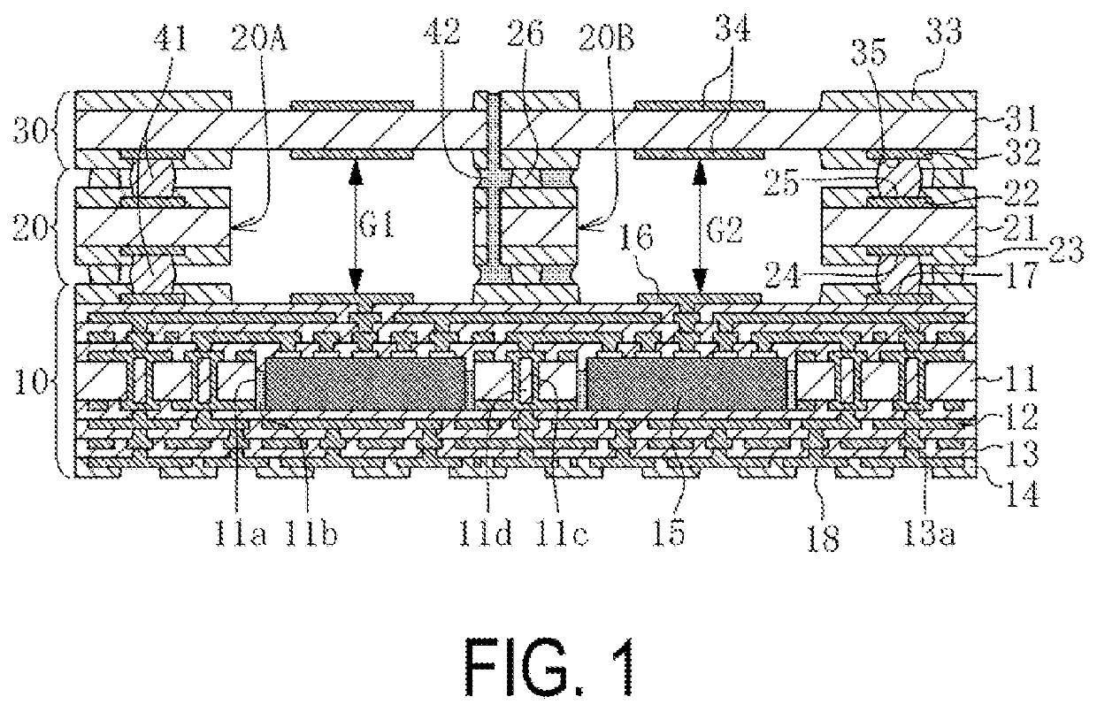
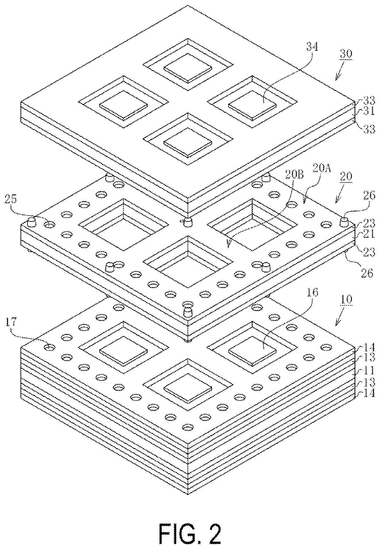
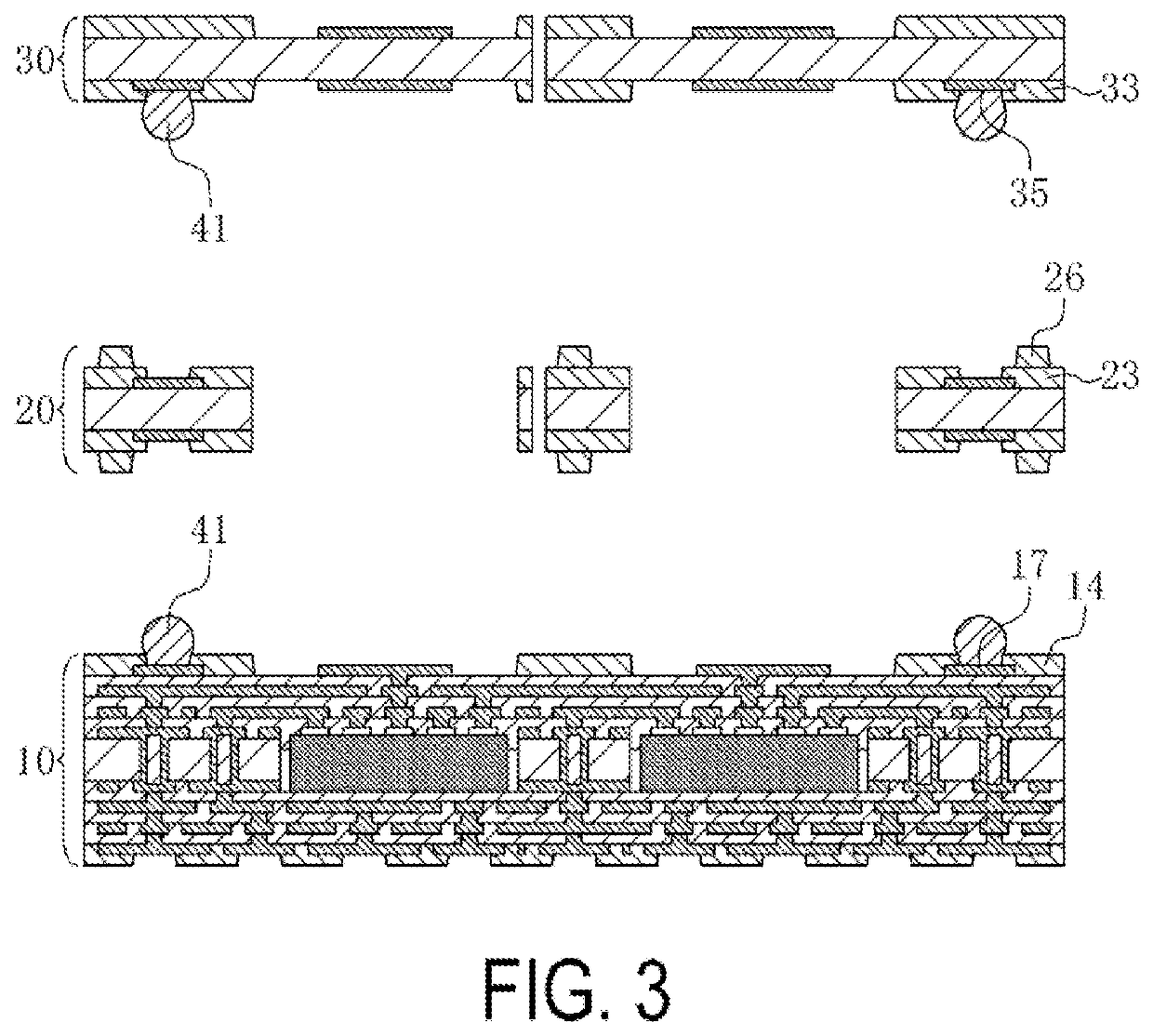
[0019]A first example of an embodiment of the present disclosure is illustrated in a schematic cross-sectional view in FIG. 1 and in a schematic exploded perspective view in FIG. 2. An antenna module of the present example includes a control substrate 10, a frame substrate 20, and an antenna substrate 30. The control substrate 10, the frame substrate 20, and the antenna substrate 30 are bonded via bonding members 41 and 42. The bonding member 41 is, for example, solder. The bonding member 42 is, for example, a thermosetting resin.

[0020]The control substrate 10 is formed by alternately laminating a plurality of electrical conductor layers 12 and insulating layers 13 on upper and lower surfaces of an insulating plate 11. A solder-resist layer 14 is adhered to upper and lower surfaces of the control substrate 10. The control substrate 10 has a square, flat plate shape. A semiconductor element 15 is housed inside the control substrate 10.

[0021]The insulating plate 11 is made from an ele...


PUM


Abstract

An antenna module of the present disclosure includes a control substrate having a flat plate shape and configured to house or mount a semiconductor element; a frame substrate bonded to an upper surface of the control substrate via bonding members and exposing a center portion of the upper surface of the control substrate; and an antenna substrate having a flat plate shape, bonded to an upper surface of the frame substrate via the bonding members so as to face the control substrate, and provided with a plurality of antenna patterns disposed along a main surface of the antenna substrate. The frame substrate includes a frame main body and a crosspiece. Between the frame main body / the crosspiece and the control substrate as well as the antenna substrate, projecting portions that come into contact with the opposing control substrate, frame substrate, and antenna substrate are provided at a fixed height.

Description

TECHNICAL FIELD[0001]The present disclosure relates to an antenna module.BACKGROUND ART[0002]An antenna module includes a control substrate, a frame substrate, and an antenna substrate. The control substrate, the frame substrate, and the antenna substrate are bonded via a bonding member. The bonding member is, for example, solder. Examples of such an antenna module include that in Patent Document 1.[0003]According to the antenna module in the related art, variations may occur in a thickness of the bonding member made from solder, and warping may occur in the antenna substrate. As a result, a spacing and parallelism between the control substrate and the antenna substrate have been susceptible to variation. When variations occur in a distance and / or the parallelism between the control substrate and the antenna substrate, a significant variation occurs in frequency characteristics of the antenna module, making it no longer possible to favorably transmit and receive high-frequency signa...

Claims


Application Information

Patent Timeline
Patent Type & Authority Patents(United States)
IPC IPC(8): H01Q1/38H01L23/66H01Q21/06H01Q23/00H05K1/14H05K3/28
CPCH01Q1/38H01L23/66H01Q21/06H01Q23/00H05K1/144H05K3/28H01L2223/6677H05K2201/20H05K1/14H01Q9/0457H01Q21/065H01Q1/2283
Inventor SAKURAI, KEIZOU
Owner KYOCERA CORP
Why Eureka
Try Eureka