
Quick change shock mitigation outsole insert with energy harvester

a technology of energy harvester and shock mitigation, which is applied in the direction of shoes, top-pieces, heels, etc., can solve the problems of inability to easily adjust the characteristics of the shock absorber, especially the load capacity, and the structure is bulky and heavy, so as to reduce the shock to the body, add lift and propulsion, and reduce fatigue

Active Publication Date: 2021-03-30
B&B TECH LP
View PDF72 Cites 4 Cited by
  • Summary
  • Abstract
  • Description
  • Claims
  • Application Information

AI Technical Summary

Benefits of technology

[0005]It is an object of the present invention to provide new and improved items of footwear which have improved shock absorbing properties and which also add lift and propulsion to the foot of a wearer when walking or running.
[0006]An object of the invention is to provide an article of footwear having an improved, easily replaceable, spring insert in the heel.
[0008]A further object is to provide a modular article of footwear, which can be quickly rebuilt, replaced, or modified by the wearer.
[0011]The insert snaps into the heel cavity, so that it can be easily and quickly replaced, for example, for wearers of different weights.
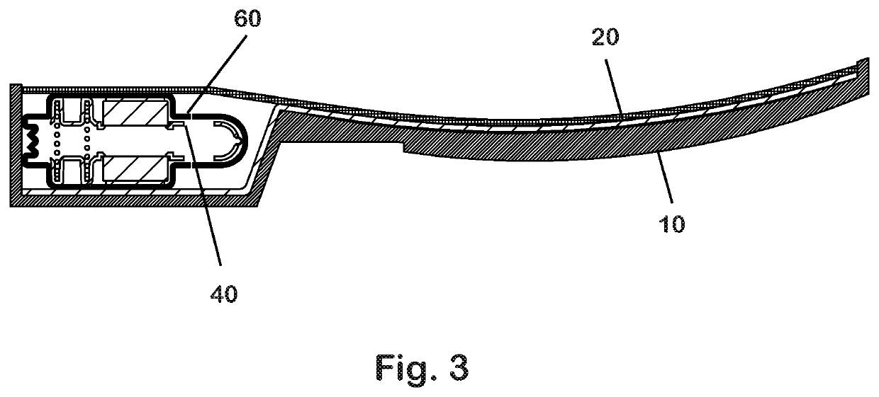
[0012]The coil springs and magnetic spring together are designed to support an air-flux gap within the sole member at all times. This permits continuous and more effective shock dissipation than when the gap is closed, solid or absent under load.
[0015]The shock absorbing insert of this invention may be used in any type of footwear, such as sports / athletic shoes, boots, casual shoes, work shoes, children's shoes, orthopedic shoes, sandals and the like. It significantly reduces shock to the body while walking, running or in other types of foot motion, and adds lift and propulsion, thereby reducing fatigue.

Problems solved by technology

Some of these structures are bulky and heavy, or cannot effectively be manufactured.
One problem with prior shock absorbing footwear, including my own, is that the characteristics of the shock absorber, particularly including the load capacity, cannot be easily adjusted.

Method used


Image

  • Quick change shock mitigation outsole insert with energy harvester
  • Quick change shock mitigation outsole insert with energy harvester
  • Quick change shock mitigation outsole insert with energy harvester

Examples


Embodiment Construction

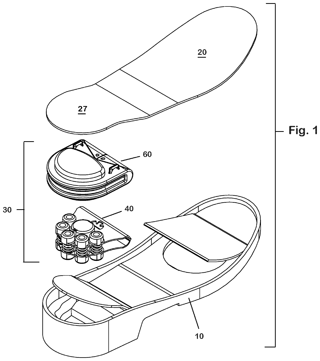
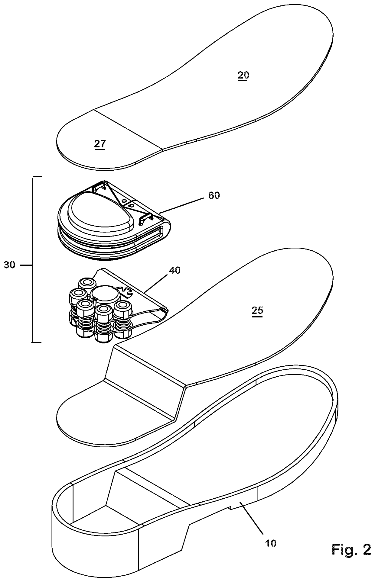
[0028]As shown in FIGS. 1 and 2, which depict two embodiments of the invention, shock absorbing footwear embodying the invention includes an outsole 10, an insole 20, and an insert assembly 30.

[0029]The outsole 10 is preferably made of rubber, EVA, composite or polyurethane.

[0030]It has an open heel cavity or a similar cavity beneath the ball of the foot, approximately as wide as the heel or ball, 2.5″ for example. FIG. 2 shows the heel cavity only, as an example. The reader will understand that the principles illustrated can easily be adapted to an insert placed beneath the ball of the foot (as suggested in FIG. 1) rather than—or in addition to—at the heel location.

[0031]The heel cavity has an opening on one side, e.g., toward to the arch or heel, approximately 3.0″ wide, for receiving the insert assembly.

[0032]The outsole has a perimeter bead made of rubber, eva, composite or polyurethane. Alternatively, it may have multiple beads (upper and lower) to allow the insert to be manual...


PUM


Abstract

A modular article of footwear has a shock absorbing insert placed between the insole and the outsole thereof, for example at the heel. The insert includes a spring carrier having upper and lower portions, each having a plurality seats for receiving a respective ends of respective coil springs. Each of the springs extends between said upper and lower portions and is captured therebetween. A pair of opposed permanent magnets generates a separating force which supplements the supporting force of the mechanical springs. The insert may also contain a device for converting mechanical energy to electrical energy.

Description

[0001]This application is a continuation-in-part of application Ser. No. 14 / 330,451 filed Jul. 14, 2014, which claims benefit of provisional application 61 / 957,910, filed Jul. 15, 2013.BACKGROUND OF THE INVENTION[0002]This invention relates to shock absorbing footwear.[0003]Numerous footwear inventions have been proposed for absorbing shock and adding lift, particularly in the athletic shoe field. For example, U.S. Pat. No. 4,817,304 describes footwear with a cushioning sole structure in which a sealed internal member in the sole is inflated with gas to form a resilient insert in the heel region of the shoe. Various shoe structures have also been proposed in which springs are embedded in the shoe sole in the heel region or over the entire sole. See, for example, U.S. Pat. Nos. 5,502,901, 5,138,776, 4,566,206, and 4,592,153. Some of these structures are bulky and heavy, or cannot effectively be manufactured. My own patents (U.S. Pat. Nos. 5,502,901 and 7,213,350) describe improvement...

Claims


Application Information

Patent Timeline
Patent Type & Authority Patents(United States)
IPC IPC(8): A43B13/18A43B21/30A43B7/14A43B1/00A43B21/00A43B3/00A43B21/24
CPCA43B13/182A43B1/0054A43B3/0015A43B7/144A43B7/1445A43B7/1465A43B21/00A43B21/30A43B21/24A43B3/38A43B7/1464A43B13/37
Inventor BROWN, JEFFREY W.
Owner B&B TECH LP
Learn More