Coil spacer structure for molding transformer
a transformer and spacer technology, applied in transformers/inductance coils/windings/connections, transformers/inductance details, electrical equipment, etc., can solve the problems of difficult problems in minimizing and thecreepage distance required to endure a high lightning impulse voltage is insufficient, so as to minimize the arcing distance in the air
- Summary
- Abstract
- Description
- Claims
- Application Information
AI Technical Summary
Benefits of technology
Problems solved by technology
Method used
Image
Examples
first embodiment
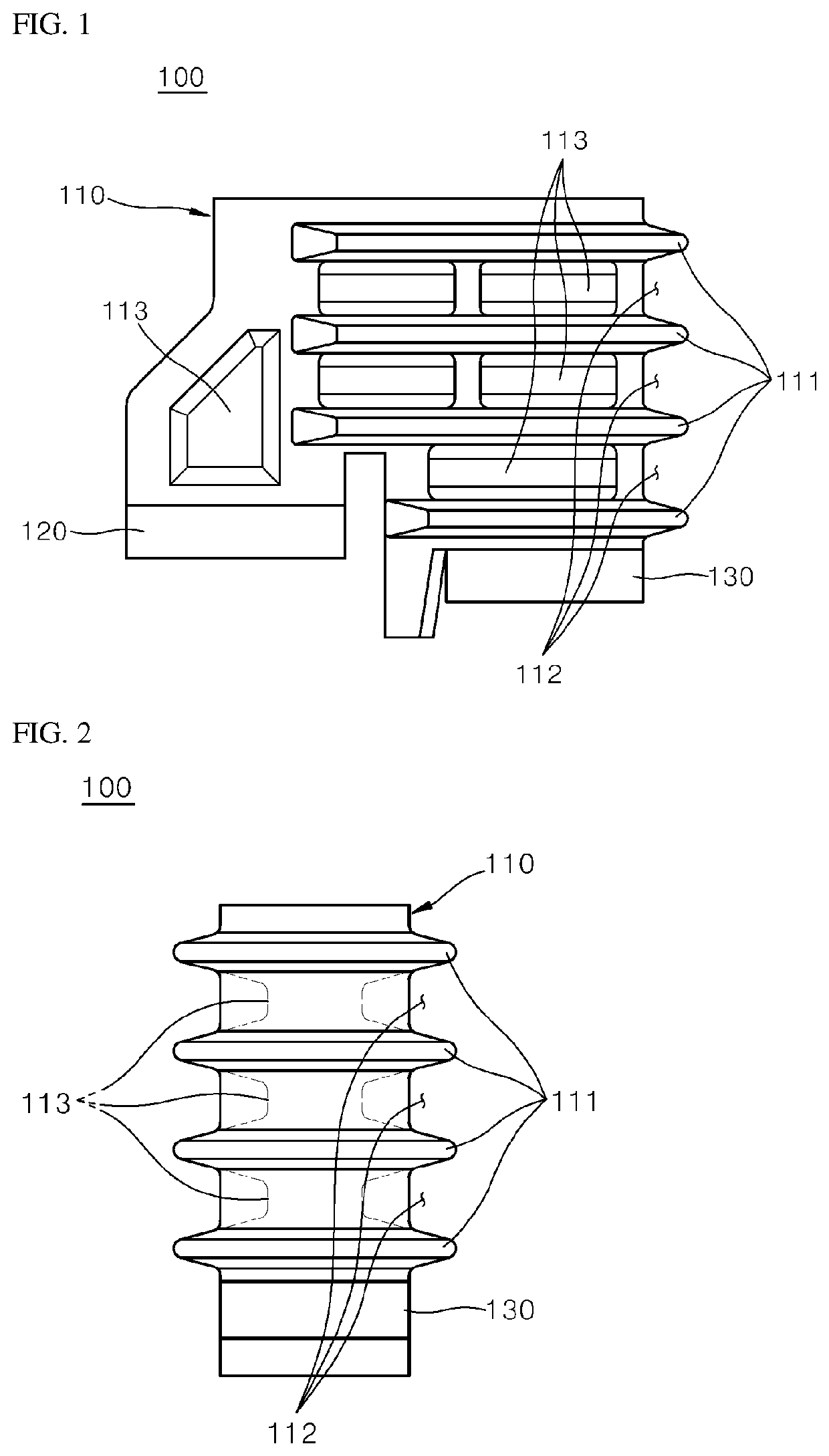
[0028]FIG. 1 is a perspective view schematically illustrating a coil spacer structure for a molding transformer according to the present disclosure, and FIG. 2 is a schematic side view of the coil spacer structure illustrated in FIG. 1.
[0029]As illustrated, the coil spacer structure 100 includes a body block 110, a low tension coil support member 120, and a high tension coil support member 130.
[0030]More specifically, the body block 110 may be positioned at the upper and lower portions of a high tension coil to support the coil and to maintain the arcing distance in the air among the high tension coil, an iron core, and a spacer tightening bolt in order to endure the lightning impulse withstand voltage.
[0031]To this end, the low tension coil support member 120 may be coupled to one end of the body block 110, and the high tension coil support member 130 may be coupled to the other end thereof.
[0032]In addition, the body block 110 includes a plurality of protrusions 111, a plurality o...
second embodiment
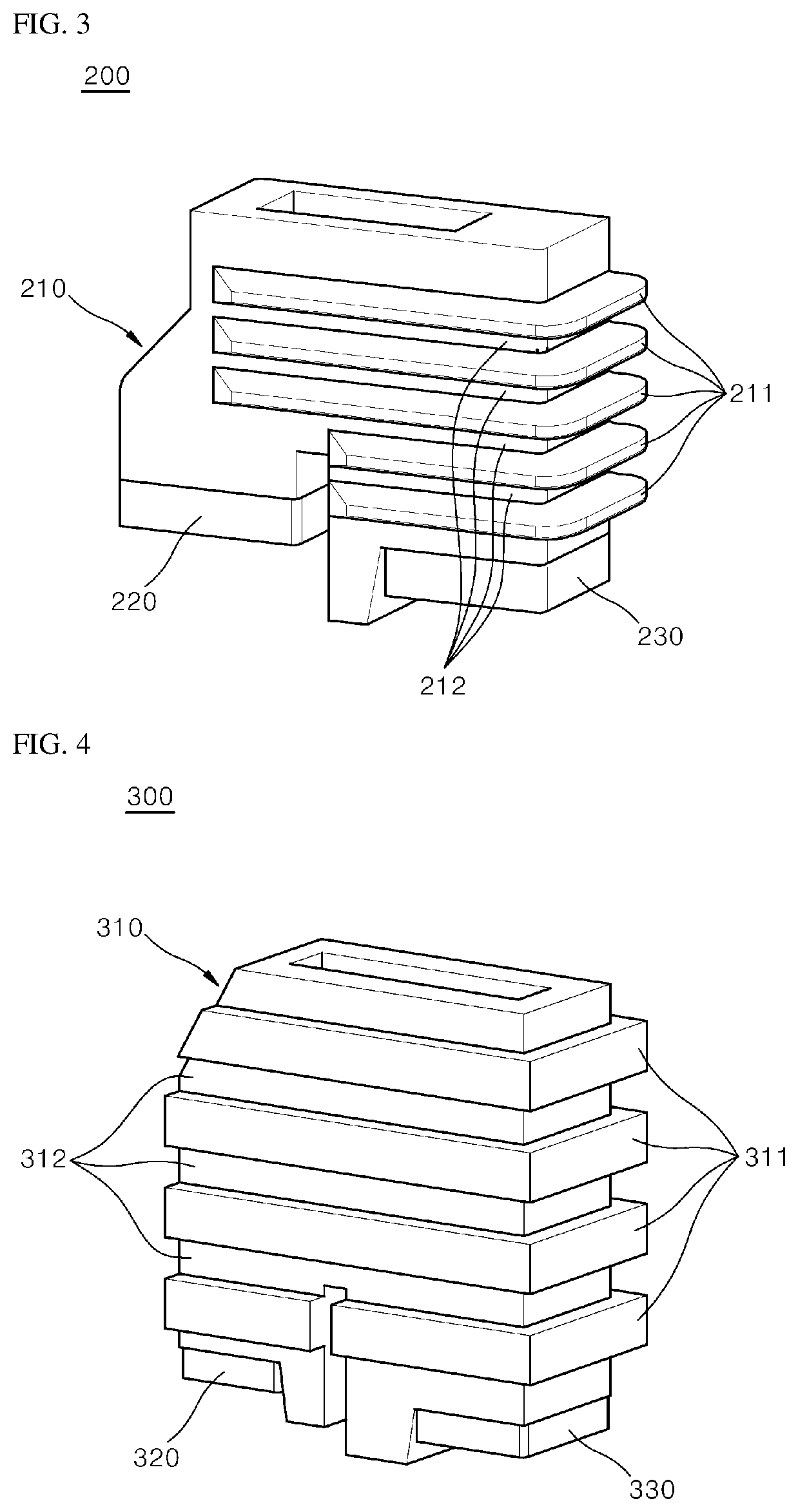
[0037]FIG. 3 is a perspective view schematically illustrating a coil spacer structure for a molding transformer according to the present disclosure.
[0038]As illustrated, the coil spacer structure 200 includes a body block 210, a low tension coil support member 220, and a high tension coil support member 230.
[0039]More specifically, the low tension coil support member 220 may be coupled to one end of the body block 210, and the high tension coil support member 230 may be coupled to the other end thereof.
[0040]In addition, the body block 210 includes a plurality of protrusions 211 and a plurality of grooves 212. The plurality of protrusions 211 may be continuously formed on an outer peripheral portion of the body block 210 at regular intervals.
[0041]In addition, the plurality of protrusions 211 may be formed to have a curved surface.
[0042]Further, the plurality of grooves 212 may be formed between adjacent protrusions 111 so as to correspond to the plurality of protrusions 211.
[0043]U...
third embodiment
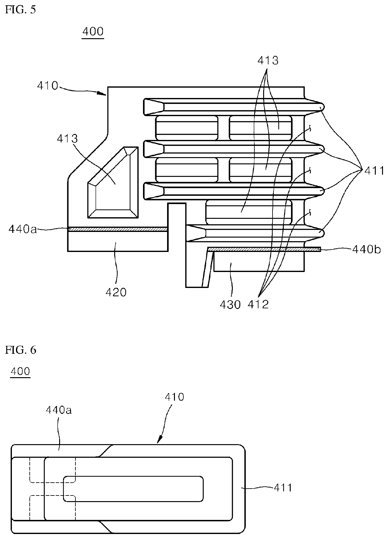
[0044]FIG. 4 is a perspective view schematically illustrating a coil spacer structure for a molding transformer according to the present disclosure.
[0045]As illustrated, the coil spacer structure 300 includes a body block 310, a low tension coil support member 320, and a high tension coil support member 330.
[0046]In addition, the coil spacer structure 300 according to the third embodiment differs from the coil spacer structure 200 according to the second embodiment only in the shape of a plurality of protrusions.
[0047]More specifically, the body block 310 includes a plurality of protrusions 311 and a plurality of grooves 312. The plurality of protrusions 311 are continuously formed on an outer peripheral portion of the body block 310 at regular intervals.
[0048]Also, the outer peripheral surface of the plurality of protrusions 311 may be formed to have parallel surfaces corresponding to the plurality of grooves 312.
PUM
| Property | Measurement | Unit |
|---|---|---|
| tension | aaaaa | aaaaa |
| voltage | aaaaa | aaaaa |
| specific voltage | aaaaa | aaaaa |
Abstract
Description
Claims
Application Information
 - R&D
- Intellectual Property
- Life Sciences
- Materials
- Tech Scout
- Unparalleled Data Quality
- Higher Quality Content
- 60% Fewer Hallucinations
Browse by: Latest US Patents, China's latest patents, Technical Efficacy Thesaurus, Application Domain, Technology Topic, Popular Technical Reports.
© 2025 PatSnap. All rights reserved.Legal|Privacy policy|Modern Slavery Act Transparency Statement|Sitemap|About US| Contact US: help@patsnap.com


