
Oxygen-reducing installation and method for operating an oxygen-reducing installation

a technology of oxygen-reducing installation and oxygen-reducing method, which is applied in the field of oxygen-reducing installation, can solve the problem of not being able to be implemented in view of investment cos

Active Publication Date: 2021-03-02
WAGNER FIRE SAFETY INC
View PDF22 Cites 0 Cited by
  • Summary
  • Abstract
  • Description
  • Claims
  • Application Information

AI Technical Summary

Problems solved by technology

In order to be able to realise this solely with a gas separation system the gas separation system would have to be correspondingly large in configuration, which as a rule cannot be implemented in view of investment costs.

Method used


Image

  • Oxygen-reducing installation and method for operating an oxygen-reducing installation
  • Oxygen-reducing installation and method for operating an oxygen-reducing installation
  • Oxygen-reducing installation and method for operating an oxygen-reducing installation

Examples


Embodiment Construction

[0043]The present invention is based on the problem that after a conventional oxygen-reducing installation has been triggered, i.e. when the oxygen-reduced gas mixture or inert gas stored in compressed form in the compressed gas storage has been passed into the enclosed space for the rapid or first lowering, replacement of the compressed gas storage which has then been emptied or partially emptied with a full compressed gas storage is unavoidable, in order to ensure that a rapid lowering according to a given course of events can also be realised again with the oxygen-reducing installation at a later point in time.

[0044]In many cases, however, replacement or changing of the compressed gas storage can be realised only with increased outlay, since the compressed gas storage of an oxygen-reducing installation often is not arranged freely accessibly. This circumstance also leads inter alia to the running operating costs of an oxygen-reducing installation often being relatively high.

[0045...


PUM


Abstract

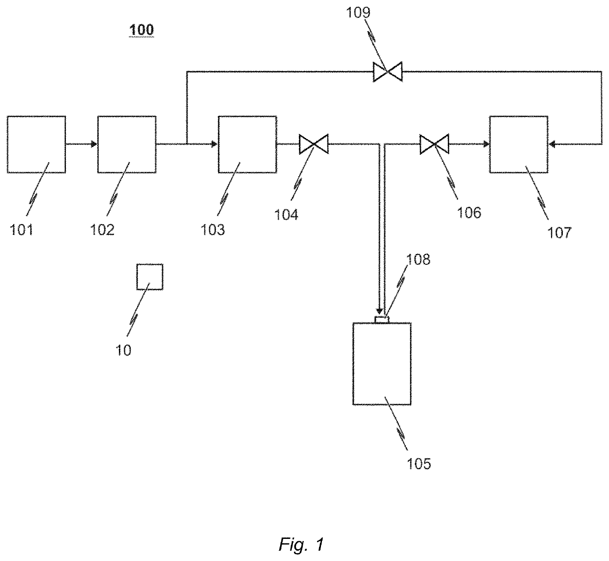
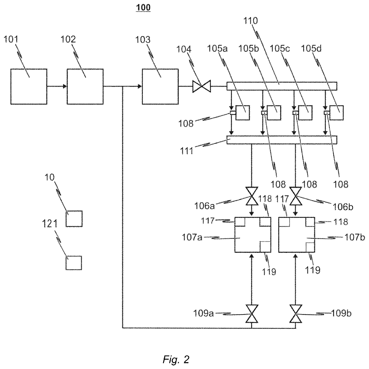
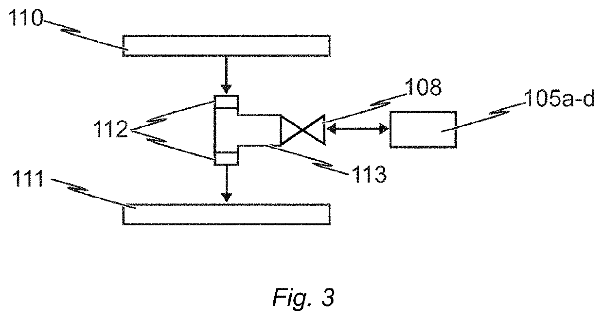
An oxygen-reducing installation and method include a compressed gas storage having a container for storing a compressed gas, which can be an oxygen-reduced gas mixture or an inert gas, and having a fluid connection to an enclosed area via a line system to feed at least a portion of the compressed gas to the enclosed area. A gas separation system provides an oxygen-reduced gas mixture and includes an outlet for delivery of the oxygen-reduced gas mixture produced in the gas separation system to the compressed gas storage and / or to the enclosed area as required.

Description

CROSS REFERENCE TO RELATED APPLICATIONS[0001]N / ASTATEMENT REGARDING FEDERALLY SPONSORED RESEARCH OR DEVELOPMENT[0002]N / AFIELD OF THE INVENTION[0003]The present invention relates to an oxygen-reducing installation and a method for operating such an installation.BACKGROUND[0004]An oxygen-reducing installation can be used to serve in particular for controlled reduction of the oxygen content in the atmosphere of an enclosed area. For this purpose, the oxygen-reducing installation has an inert gas source for providing an oxygen-reduced gas mixture or an inert gas, and a line system which is connected or can be connected with regard to flow to the inert gas source and to the enclosed area in order to feed at least some of the gas mixture or gas provided by the inert gas source to the enclosed area as required.[0005]The installation serves, for example, to reduce the risk of and to extinguish fires in a protected space which is to be monitored, wherein for fire prevention or for fire fight...

Claims


Application Information

Patent Timeline
Patent Type & Authority Patents(United States)
IPC IPC(8): A62C2/04A62C37/08A62C35/64A62C35/68A62C99/00
CPCA62C2/04A62C35/645A62C35/68A62C37/08A62C99/0018A62C99/0063
Inventor WAGNER, ERNST-WERNEREICHHOFF, JULIAN
Owner WAGNER FIRE SAFETY INC
Learn More