
Orthognathic saw and positioning implant

a technology sawing, which is applied in the field of orthognathic bone fusion implants, can solve the problems of high operating cost and relative high cost of manufacturing the elements used in osteotomy applications, and achieve the effect of reducing the expenditure of osteotomy treatmen

Active Publication Date: 2021-03-02
KARL LEIBINGER MEDIZINTECHNIK GMBH & CO KG
View PDF27 Cites 0 Cited by
  • Summary
  • Abstract
  • Description
  • Claims
  • Application Information

AI Technical Summary

Benefits of technology

[0005]Therefore, it is the object of the present invention to eliminate said drawbacks known from the state of the art and, especially, to provide a bone fusion implant which further reduces the expenditure of an osteotomy treatment, while at the same time patient-specific / individualized adaptation of the bone fusion implant is to be guaranteed.

Problems solved by technology

These configurations known from prior art usually have the drawback, however, that for a cutting processing of the respective mammalian bone to be corrected and subsequently to be fused again, for example a maxilla or mandible, two separate elements have to be used.
This required a relative expensive manufacture of the elements used for the osteotomy applications and consequently indirectly also relatively high operating costs.

Method used


Image

  • Orthognathic saw and positioning implant
  • Orthognathic saw and positioning implant
  • Orthognathic saw and positioning implant

Examples


Embodiment Construction

[0038]The Figures are merely schematic and serve exclusively for the comprehension of the invention. Like elements are provided with like reference numerals.

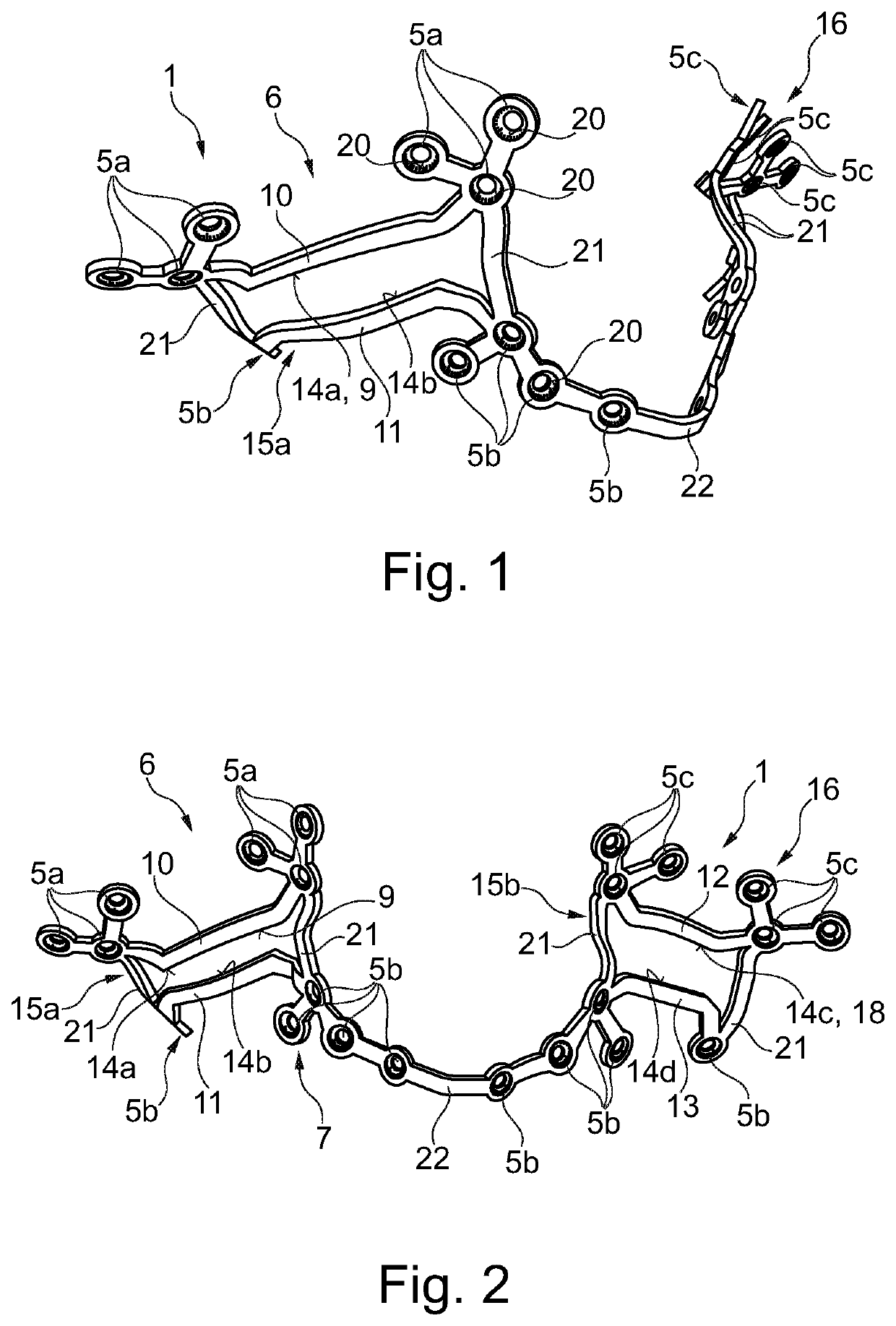
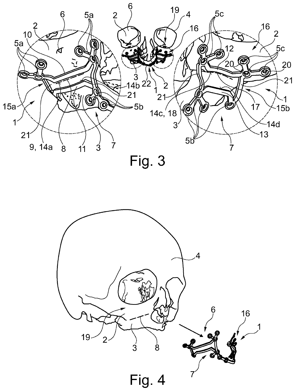
[0039]From FIG. 1 a bone fusion implant 1 according to the invention in accordance with a preferred embodiment is especially clearly evident. In this figure, especially a first fixing region 6 which has multiple securing means receiving holes 5a and is provided for attaching to a first bone region 2 of a mammalian bone 4 as well as a second fixing region 7 which is connected to the first fixing region 6 is evident. Also, the second fixing region 7 again includes multiple securing means receiving holes, hereinafter referred to as second securing means receiving holes 5b, thus allowing the second fixing region 7 to be provided for attaching to a second bone region 3 of the mammalian bone 4.

[0040]As it is then further clearly visible from FIG. 2, the second fixing region 7 which is substantially formed by means of a main bar 22 is ...


PUM


Abstract

A bone fusion implant for fusing a first bone region to a second bone region of a mammalian bone includes a first fixing region having multiple securing means receiving holes for attaching to the first bone and a second fixing region which is connected to the first fixing region and has multiple securing means receiving holes for attaching to the second bone region, wherein a cutting tool guiding contour which specifies a severing line is formed between the first and the second fixing region. A method for the individualized production of such a bone fusion implant includes recording an actual 3D model of the mammalian bone implant in a first data set, drafting a target 3D model, and producing the bone fusion implant by way of the target 3D model.

Description

BACKGROUND OF THE INVENTION[0001]The invention relates to an orthognathic bone fusion implant (also referred to as positioning implant) for an osteotomy application / for fusing a first bone region to a second bone region or plural bone regions of a mammalian bone / bone of a mammal, comprising a first fixing region which has multiple securing means receiving holes and which is provided for attaching to the first bone region and comprising a second fixing region which is connected to the first fixing region, wherein the second fixing region in turn has multiple securing means receiving holes and is provided for attaching to the second bone region. Especially when the mandible, for example, is two-parts, for example in the case of mandibular crowded teeth, there are plural bone regions to which the first bone region is fused. By a mammalian bone / a bone of a mammal an especially hard skeletogenous septum of a vertebrate is understood, hence such a structure of bone tissue. In particular t...

Claims


Application Information

Patent Timeline
Patent Type & Authority Patents(United States)
IPC IPC(8): A61B17/17A61B17/80A61B34/10A61B17/00A61B17/56
CPCA61B17/8071A61B17/176A61B17/1728A61B34/10A61B2017/00004A61B2017/568A61B2034/104A61B2034/108
Inventor WAIZENEGGER, AXEL
Owner KARL LEIBINGER MEDIZINTECHNIK GMBH & CO KG
Learn More