Eureka AIR delivers breakthrough ideas for toughest innovation challenges, trusted by R&D personnel around the world.

Method for the recognition of a moving pedestrian

a technology for moving pedestrians and recognition methods, applied in the field of moving pedestrian recognition methods, can solve problems such as additional doppler shifts, and achieve the effect of reliable recognition of moving pedestrians

Active Publication Date: 2021-02-23
APTIV TECH LTD
View PDF32 Cites 5 Cited by
  • Summary
  • Abstract
  • Description
  • Claims
  • Application Information

AI Technical Summary

Benefits of technology

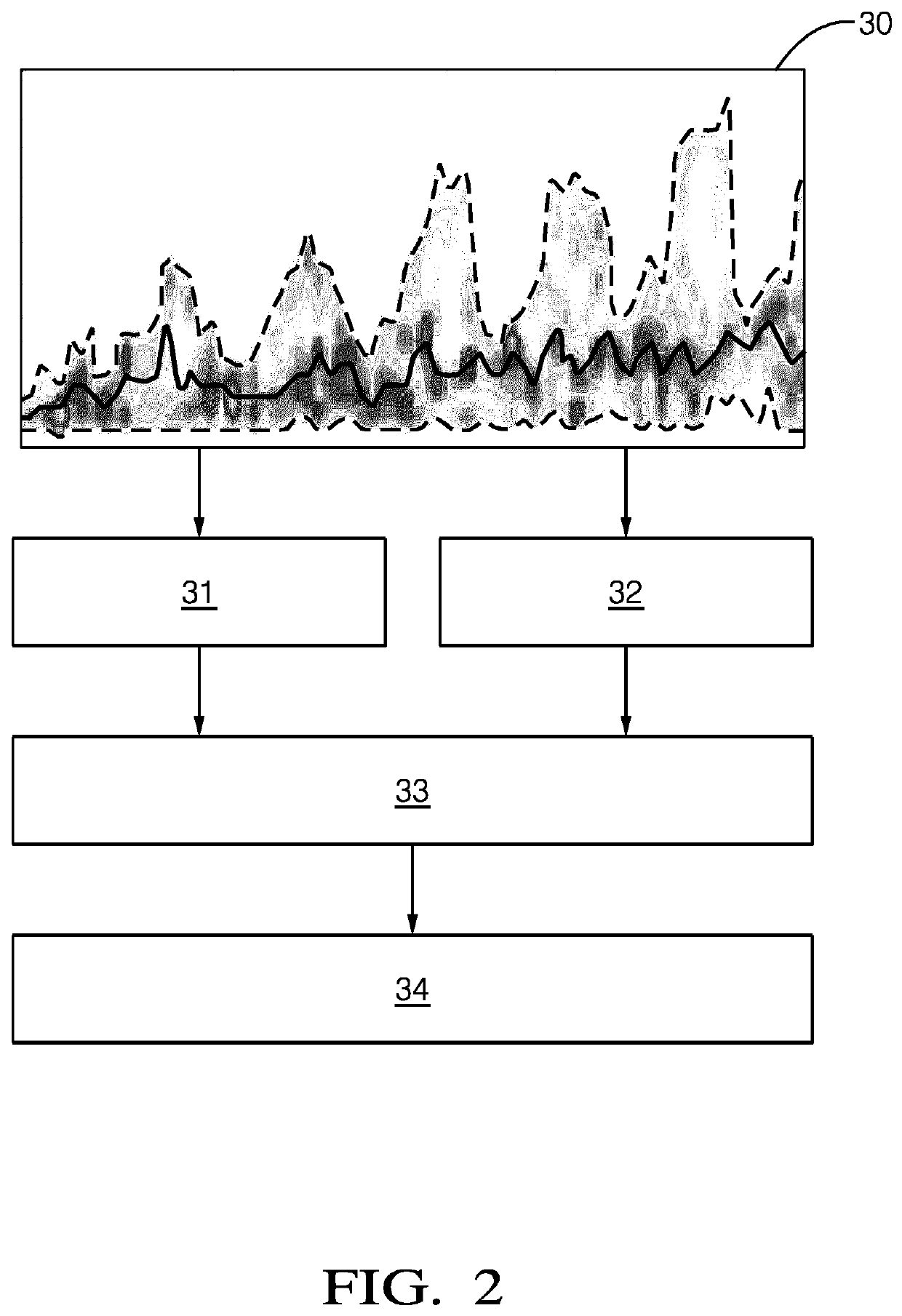
[0011]By means of a method in accordance of the invention, it is possible to determine the illumination angle in a quick and easy manner merely by analyzing the Micro-Doppler spectrogram. In the field of radar-based object recognition, the illumination angle is an important quantity to be used in various processing and evaluation steps. The knowledge of the illumination angle enables a particularly reliable detection of crossing pedestrians. In particular, the speed of a pedestrian in the moving direction can be calculated if the illumination angle is known.
[0012]In principle, the illumination angle can be estimated by means of an angle-finding process. Such a process, however, requires a multiple channel radar system, which is rather costly. In contrast, a method in accordance with the invention is not dependent on the presence of a multiple channel radar sensor and may be implemented directly in the range-Doppler domain. The invention thus enables the fabrication of low-cost pedestrian recognition systems.
[0022]In accordance with an embodiment of the invention, the overall height of the moving pedestrian is estimated based on a statistical average height of pedestrians. It has shown that the typical height of pedestrians is between 1.2 m and 1.8 m. Therefore, Hped may be set to 1.5 m. This enables a simple calculation of the illumination angle.

Problems solved by technology

For example, swinging arms or legs of a pedestrian can cause additional Doppler shifts.

Method used


Image

  • Method for the recognition of a moving pedestrian
  • Method for the recognition of a moving pedestrian
  • Method for the recognition of a moving pedestrian

Examples


Embodiment Construction

[0039]Reference will now be made in detail to embodiments, examples of which are illustrated in the accompanying drawings. In the following detailed description, numerous specific details are set forth in order to provide a thorough understanding of the various described embodiments. However, it will be apparent to one of ordinary skill in the art that the various described embodiments may be practiced without these specific details. In other instances, well-known methods, procedures, components, circuits, and networks have not been described in detail so as not to unnecessarily obscure aspects of the embodiments.

[0040]‘One or more’ includes a function being performed by one element, a function being performed by more than one element, e.g., in a distributed fashion, several functions being performed by one element, several functions being performed by several elements, or any combination of the above.

[0041]It will also be understood that, although the terms first, second, etc. are,...


PUM


Abstract

A method for the recognition of a moving pedestrian by means of a radar sensor system includes the steps of transmitting a primary radar signal into an observation space and of receiving a secondary radar signal reflected by the moving pedestrian. The secondary radar signal is processed, wherein the processing of the secondary radar signal includes the steps of generating a Micro-Doppler spectro-gram of the secondary radar signal, determining, based on the Micro-Doppler spectrogram, an observed bulk speed of the moving pedestrian, determining, based on the Micro-Doppler spectrogram, at least one gait cycle parameter of the moving pedestrian and determining, based on the determined observed bulk speed and the determined gait cycle parameter, an illumination angle between a moving direction of the moving pedestrian and the line of sight.

Description

TECHNICAL FIELD OF INVENTION[0001]The present invention relates to a method for the recognition of a moving pedestrian by means of a radar sensor system, wherein a primary radar signal is transmitted into an observation space, and a secondary radar signal reflected by the moving pedestrian is received and processed.BACKGROUND OF INVENTION[0002]Radar sensor systems are used in a wide range of applications. For example, modern motor vehicles are often equipped with radar sensor systems to detect other vehicles, obstacles or vulnerable road users such as pedestrians or cyclists. A detection and classification of objects in a traffic space from a host vehicle is in particular needed for various advanced driver assistance systems (ADAS), such as advanced emergency braking (AEB) systems, collision avoidance systems and autonomous driving systems. Often, the known Doppler effect is used to gather information relating to moving objects. The Doppler effect or Doppler shift is a change in fre...

Claims


Application Information

Patent Timeline
Patent Type & Authority Patents(United States)
IPC IPC(8): G06K9/00G01S13/58G01S13/931
CPCG06K9/00348G01S13/58G06K9/00369G01S13/931G01S13/50G01S13/62G01S7/415G01S13/46G01S13/589G01S2013/93271G06V40/25G06V40/103
Inventor YAN, HONGHUIZHANG, TAODOERR, WOLFGANGIOFFE, ALEXANDER
Owner APTIV TECH LTD
Why Eureka
Eureka Blog
Learn More