
Push button device for timepieces

a push button and timepiece technology, applied in the field of push button devices for timepieces, can solve the problems of inability to bring the push button head, the method of assembling such push button devices is not suitable for these push buttons, and the situation is evidently unacceptabl

Active Publication Date: 2021-02-23
OMEGA SA
View PDF7 Cites 1 Cited by
  • Summary
  • Abstract
  • Description
  • Claims
  • Application Information

AI Technical Summary

Benefits of technology

The present invention provides a push button device with a simple and economical design that allows for easy adjustment of the position of a logo or trademark on the push button head. The device has a central shaft that can be rotated, which causes the push button to pivot against the friction ring, thus adjusting the angular orientation of the head. This allows for precise and accurate positioning of the logo or trademark, improving the overall appearance of the push button device.

Problems solved by technology

However, methods for assembling such push button devices are ill suited to these push buttons when the push button bears an inscription or a motif, for example a logo, a trademark or similar sign, on its head end face.
Indeed, known assembly methods do not generally allow the push button head to be brought into a determined precise angular orientation with respect to the case when the push button device is assembled by screwing or pressing the tube into the watch case.
This situation is evidently unacceptable when these push button devices are fitted to high quality and luxury products.

Method used


Image

  • Push button device for timepieces

Examples


Embodiment Construction

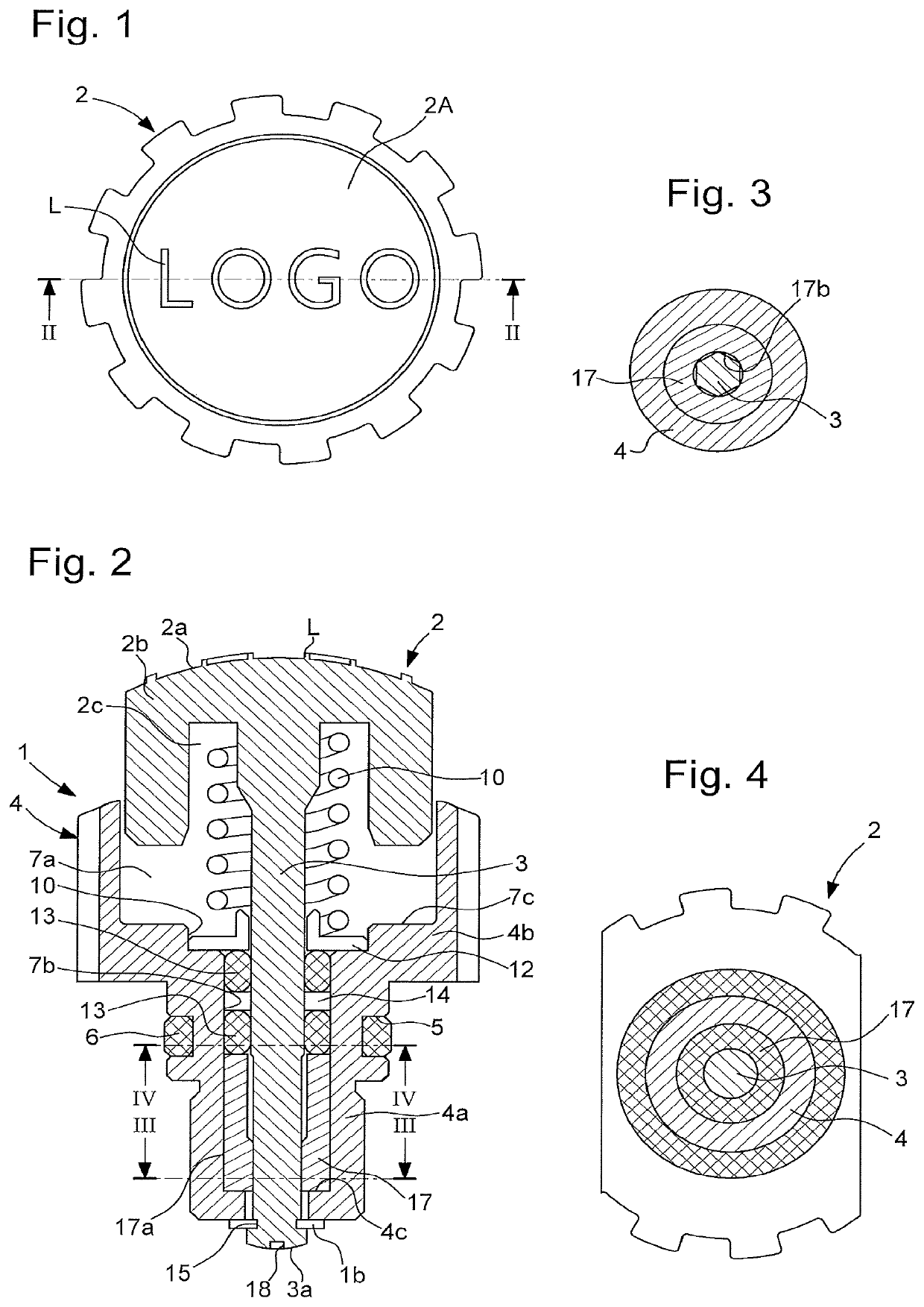
[0032]FIGS. 1 and 2 show a push button device 1 including an orientable push button head 2a and intended to be mounted by being pressed or screwed into the side wall of a watch case middle (not represented).

[0033]In FIG. 1, which is a top view of push button device 1, the inscription ‘LOGO’ can be seen, arranged on the external face 2a of head 2b of push button 2. Push button device 1 includes orientation adjustment means which will be described below with reference to FIGS. 2 to 4. For aesthetic reasons, the inscription ‘LOGO’ L is adjusted in a perfectly horizontal position, preferably corresponding to the plane of the middle part of the watch in which push button device 1 is mounted.

[0034]Push button device 1 includes a push button 3 which is provided at a proximal end with a push button head 2b to allow a user to actuate the push button. Push button head 2b is integral with a central shaft 3 which ensures, at a distal end, the connection between the interior and the exterior of ...


PUM


Abstract

A push button device including a device for adjusting the angular orientation of the push button head with respect to the watch case, wherein the angular orientation adjustment device includes a friction ring disposed concentrically around the central shaft inside the tube, the friction ring rotates integrally with the central shaft and is free in translation with respect to the central shaft, the friction ring includes an external friction surface in friction contact with an internal wall of the tube, and wherein the central shaft includes a device for actuating the latter in rotation, making it possible to pivot the push button against the frictional forces generated by the friction ring, in order to adjust the angular orientation of the push button head.

Description

BACKGROUND[0001]This application claims priority from European patent application No. 17189110.4 filed on Sep. 1, 2017, the entire disclosure of which is hereby incorporated herein by reference.[0002]The present invention concerns a push button device for timepieces, and more particularly a device of this type wherein the push button head includes a motif or a logo on its end face and wherein the motif can be oriented as desired.BRIEF SUMMARY[0003]A push button device for timepieces typically includes a cylindrical tube, through and inside which is longitudinally disposed a push button provided with a head having a lower face that abuts against a first shoulder made in the tube when manual pressure is applied to the head and with a shaft that terminates at its end in a stop member, typically a screw, limiting the axial clearance of the shaft in the tube. A sealing gasket generally surrounds the shaft and a helical return spring is wound around the shaft to return the push button to ...

Claims


Application Information

Patent Timeline
Patent Type & Authority Patents(United States)
IPC IPC(8): G04B37/10G04B3/04
CPCG04B37/106G04B3/048G04B27/00
Inventor LOETSCHER, PHILIPPE
Owner OMEGA SA
Learn More