
Method of, and apparatus for, full waveform inversion

a full waveform and waveform technology, applied in the field of full waveform inversion methods and apparatuses, can solve the problems of how accurate the starting model needs, the method can fail, and the resolution and accuracy are potentially far higher, so as to maximize and/or minimize the effect of maximizing and/or minimizing

Active Publication Date: 2021-02-23
IMPERIAL INNOVATIONS LTD
View PDF16 Cites 4 Cited by
  • Summary
  • Abstract
  • Description
  • Claims
  • Application Information

AI Technical Summary

Benefits of technology

The patent text describes a method for improving the accuracy of subsurface exploration in the field of geophysical imaging. The method involves using a convolutional filter to eliminate cycle-skipping, which can occur when data is skipped around in a repeating pattern. By eliminating cycle-skipping, the convolutional filter is still able to match two datasets that may have different patterns. The method also includes steps for generating a geophysical representation of the subsurface, generating a predicted seismic data set, and using the predicted data set to generate objective functions to measure the similarity and mismatch between the observed seismic data and the predicted data set. These objective functions are then modified to obtain an updated subsurface model for more accurate exploration. The technical effects of this method include improved accuracy for subsurface exploration and the ability to better understand the structure of the underground portion of the Earth.

Problems solved by technology

However, this need not be the case and other arrangements are possible.
The final model has potentially far higher resolution and accuracy however the method can fail due to the sensitivity of the predicted waveforms to the model.
However, the global minimum broadens at lower frequencies reducing how accurate the starting model needs to be for localized inversion to be successful.
However, in the frequency domain the data will in general be complex, as will the source and sometimes the model properties.
If the number of model parameters M is large, then calculating the Hessian is computationally demanding, and inverting the Hessian exactly is normally computationally intractable.
Further, additional constraints may be placed upon model updates and / or recovered model.
However, there are some difficulties associated with obtaining correct convergence.
However, real seismic data are limited in their frequency bandwidth.
This means that real seismic signals are oscillatory.
An inaccurate starting model may predict data that are more than half a cycle in error with respect to the observed data.
This misalignment to the nearest cycle will reduce the data misfit, and typical FWI schemes will become stranded in this position—they will have become stuck in a local minimum in the data misfit function rather than being able to find the global minimum which corresponds to the true model.
However, in practice, such an accurate starting model is unlikely given the lack of information about subsurface structures of real-world portions of the Earth. FIGS. 6d) to 6f) illustrate the operation of FWI when provided with a poor (inaccurate) starting model as shown in FIG. 6d).
Features are not resolved clearly, and are inaccurately located.
This is a result of cycle skipped mis-convergence and, in practice, would give a sub-optimal final result which could lead to inaccurate identification of natural resources or other sites of interest.
In practice, obtaining an accurate starting model can be difficult, time-consuming, expensive or impossible to achieve.
Obtaining sufficiently low frequencies in the observed data can be expensive or impossible to achieve in practice, and this requirement can invalidate the application of the technique to existing legacy datasets.
As a result, cycle skipping, both in the context methods that are based upon minimizing the data residuals and those based upon maximizing the cross-correlation, can compromise and limit the broad applicability and practical uptake of FWI.
Therefore, to date, known FWI methods suffer from a technical problem that cycle skipped mis-convergence can lead to significant errors in a final, generated model of a subsurface portion of the Earth.
Attempts to address this in practice often have significant limitations with regard to the size, complexity and / or cost of models and computational processing required.
In this situation, the normalized secondary objective function is insensitive or of limited sensitivity to the value of the scaling applied to the reference coefficients.

Method used


Image

  • Method of, and apparatus for, full waveform inversion
  • Method of, and apparatus for, full waveform inversion
  • Method of, and apparatus for, full waveform inversion

Examples


first embodiment

[0152]A method according to the present disclosure will now be described with reference to FIG. 7. FIG. 7 shows a flow diagram of the present disclosure.

[0153]Step 100: Obtain Observed Seismic Data Set

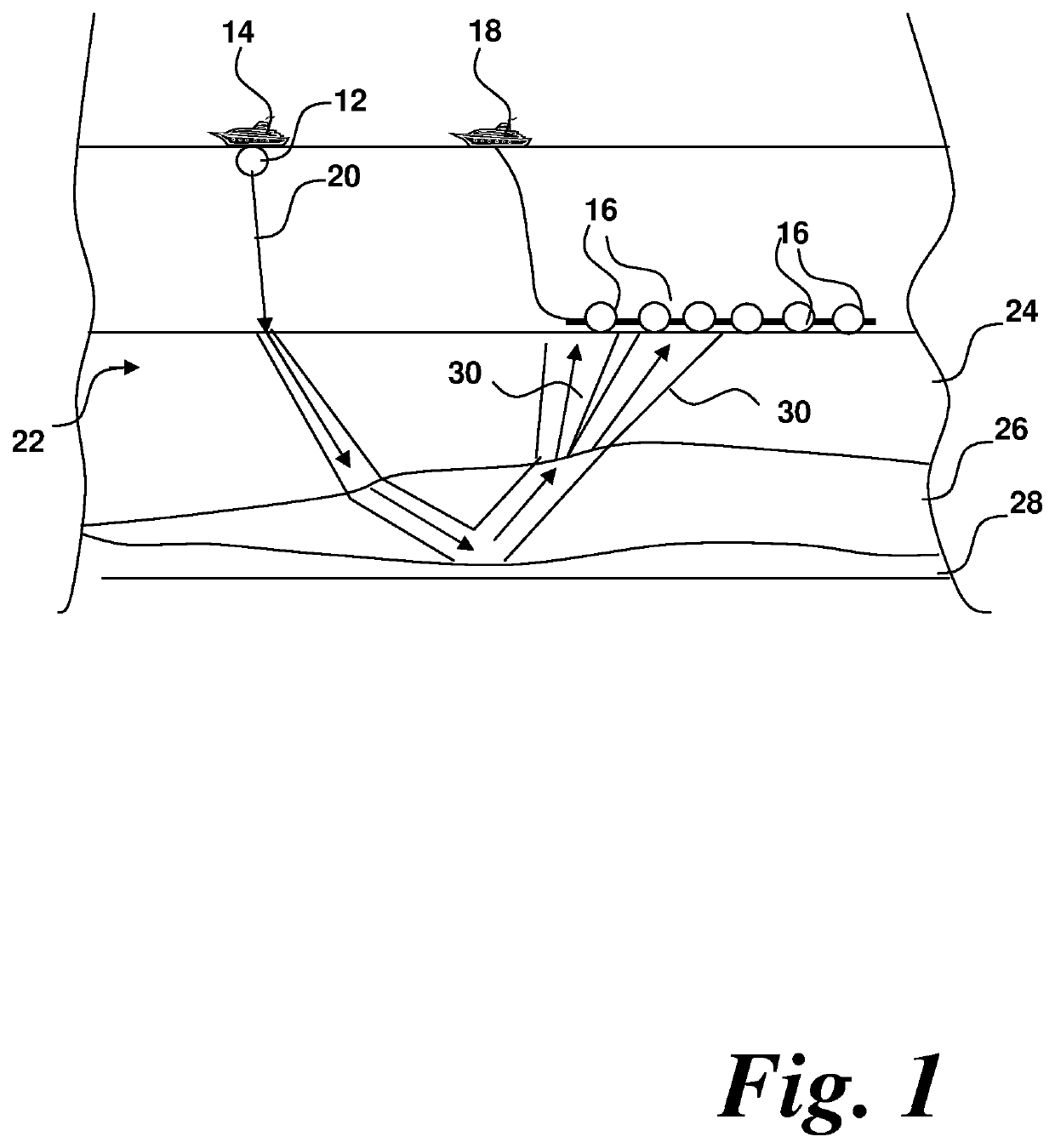
[0154]Initially, it is necessary to obtain a set of experimentally gathered seismic data in order to initiate subsurface exploration. This may be gathered by an experimental arrangement such as the set up shown and described with reference to FIG. 1.

[0155]The gathered seismic data may be optionally pre-processed in various ways including by propagating numerically to regions of the surface or subsurface where experimental data have not been acquired directly. The skilled person would readily be able to design and undertake such pre-processing as might be necessary or desirable. With or without such pre-processing, the resultant seismic dataset representing experimentally-gathered data is known as an “observed seismic data set”.

[0156]As shown in FIG. 1, a large number of receivers or de...

third embodiment

[0225]This approach can be applied to FWI. At each receiver, for each source, a Wiener filter w can be designed that operates on the observed seismic data set dobs to convert the observed seismic data set dobs into the predicted data set dpred. In this embodiment, the filter w operates to convert the observed data into the predicted data. The third embodiment discloses an alternative approach. Equation 26) and 27) denote the approach of this embodiment.

dobs*w=dpred  26)

w=(BTB)−1BTdpred  27)

Here B is the matrix representation of convolution by dobs, and BT is the matrix representation of cross-correlation with dobs. The method proceeds to step 210.

[0226]Step 210: Generate Reference Filter

[0227]Once the convolutional filter is designed in step 208, an analogous convolutional filter is designed such that, when applied to an input dataset, this reference filter will generate an output dataset that provides an equivalent approximation to all or parts of the input dataset. In other words,...


PUM


Abstract

A method of subsurface exploration includes generating a representation of a portional volume of the Earth from a seismic measurement of a physical parameter. The method includes providing observed seismic dataset having three distinct nonzero data values derived from three distinct nonzero seismic measured values of said portional volume of the Earth, generating a predicted seismic dataset having three distinct nonzero data values, generating a nontrivial convolutional filter including three nonzero filter coefficients, generating a convolved observed dataset by convolving the convolutional filter with said observed seismic dataset, generating primary objective functions to measure the similarity between said convolved observed dataset and said predicted dataset, maximizing and / or minimizing said primary objective functions by modifying at least one filter coefficient of the convolutional filter, generating predetermined reference filters having at least three reference coefficients generating secondary objective functions to measure the similarity between filter coefficients for the nontrivial filter and reference coefficients for the predetermined reference filters, and minimizing and / or maximizing said secondary objective functions by modifying a model coefficient of a subsurface model of a portion of the Earth to produce an updated subsurface model of a portion of the Earth.

Description

CROSS-REFERENCE TO RELATED APPLICATIONS[0001]This application is a 35 U.S.C. § 371 national stage application of PCT / GB2014 / 050100 filed Jan. 14, 2014, entitled “Method of, and Apparatus for, Full Waveform Inversion,” which claims priority to British application No. GB 1319095.4 filed Oct. 29, 2013, both of which are incorporated herein by reference in their entirety for all purposesBACKGROUNDField of the Disclosure[0002]The present disclosure relates to a method of, and apparatus for, full waveform inversion. More particularly, the present disclosure relates to an improved method of, and apparatus for, full waveform inversion in which cycle skipped misconvergence is mitigated or eliminated.Description of Related Art[0003]There is significant interest in surveying sections of the Earth to detect natural mineral resources or other sites of geological interest. One approach to detection of such natural features is seismic surveying. Seismic surveys are the principal means by which the...

Claims


Application Information

Patent Timeline
Patent Type & Authority Patents(United States)
IPC IPC(8): G01V1/36G01V1/28
CPCG01V1/364G01V1/282G01V2210/27G01V2210/614G01V1/303G01V1/306
Inventor WARNER, MIKEGUASCH BATALLA, LLUIS
Owner IMPERIAL INNOVATIONS LTD
Learn More