Eureka AIR delivers breakthrough ideas for toughest innovation challenges, trusted by R&D personnel around the world.

Thin-film deposition method and manufacturing method of semiconductor device

a manufacturing method and semiconductor technology, applied in chemical vapor deposition coating, coating, metallic material coating process, etc., can solve the problems of lowering the yield of a product, productivity and economic loss, soh loss due to plasma radicals, etc., to improve the loss amount and improve the loss uniformity of the pattern structure

Active Publication Date: 2021-02-09
ASM IP HLDG BV
View PDF4335 Cites 1 Cited by
  • Summary
  • Abstract
  • Description
  • Claims
  • Application Information

AI Technical Summary

Benefits of technology

[0007]One or more embodiments include a method of improving the loss amount and loss uniformity of a pattern when depositing a thin film on a pattern of a semiconductor substrate and at the same time controlling a wet etch rate (WER) of the thin film formed on the semiconductor pattern.
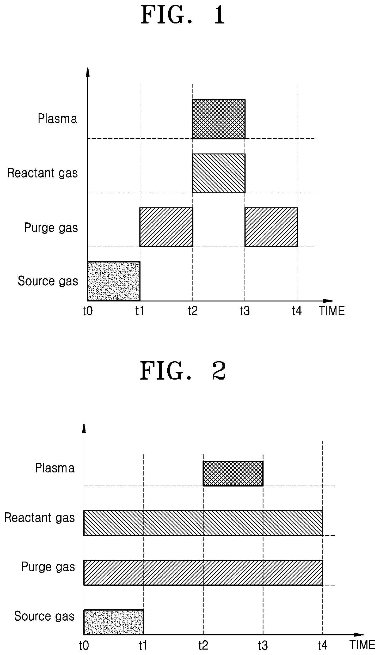
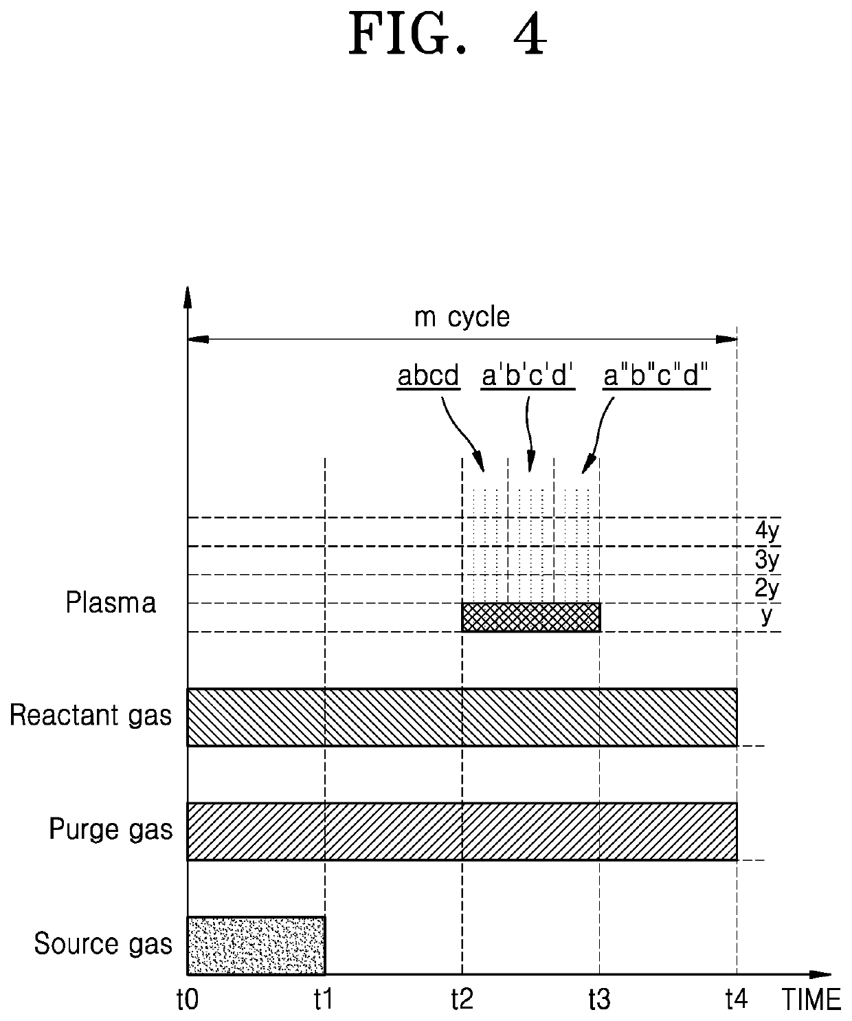
[0024]According to one or more embodiments, a method of depositing a thin film on a pattern structure of a semiconductor substrate includes: improving a loss amount and loss uniformity of the pattern structure by controlling at least one of a supply time of a source gas supply operation, plasma power and a plasma duty ratio of a plasma supply operation while using a plasma atomic layer deposition process; and controlling a wet etch rate (WER) of the thin film by controlling at least one of the plasma power and the plasma duty ratio of the plasma supply operation while using the plasma atomic layer deposition process.

Problems solved by technology

In general, when a thin film is deposited on an SOH film using a plasma process, SOH loss occurs in the SOH film due to plasma radicals.
Due to the non-uniformity of the loss, critical dimension (CD) spacing becomes irregular when fine patterning is performed, thereby lowering the yield of a product, resulting in productivity and economic loss.

Method used


Image

  • Thin-film deposition method and manufacturing method of semiconductor device
  • Thin-film deposition method and manufacturing method of semiconductor device
  • Thin-film deposition method and manufacturing method of semiconductor device

Examples


Embodiment Construction

[0036]Hereinafter, one or more embodiments will be described more fully with reference to the accompanying drawings.

[0037]In this regard, the present embodiments may have different forms and should not be construed as being limited to the descriptions set forth herein. Rather, these embodiments are provided so that the present disclosure will be thorough and complete, and will fully convey the scope of the present disclosure to one of ordinary skill in the art.

[0038]The terminology used herein is for the purpose of describing particular embodiments and is not intended to limit the present disclosure. As used herein, the singular forms “a”, “an”, and “the” are intended to include the plural forms as well, unless the context clearly indicates otherwise. It will be further understood that the terms “includes”, “comprises” and / or “including”, “comprising” used herein specify the presence of stated features, integers, steps, operations, members, components, and / or groups thereof, but do ...


PUM

PropertyMeasurementUnit
supply timeaaaaaaaaaa
plasma poweraaaaaaaaaa
plasma duty ratioaaaaaaaaaa

Abstract

A method of depositing a thin film having a desired etching characteristic while improving a loss amount and loss uniformity of a lower film includes, on the semiconductor substrate and the pattern structure: a first operation of depositing a portion of the thin film by repeating a first cycle comprising (a1) a source gas supply operation, (b1) a reactant gas supply operation, and (c1) a plasma supply operation for a certain number of times; a second operation of depositing a remaining portion of the thin film by repeating a second cycle comprising (a2) a source gas supply operation, (b2) a reactant gas supply operation, and (c2) a plasma supply operation for a certain number of times after the first operation, wherein a supply time of the source gas supply operation (a1) is longer than a supply time of the source gas supply operation (a2).

Description

CROSS-REFERENCE TO RELATED APPLICATION[0001]This application claims the benefit of Korean Patent Application No. 10-2018-0076113, filed on Jun. 29, 2018, in the Korean Intellectual Property Office, the disclosure of which is incorporated herein in its entirety by reference.BACKGROUND1. Field[0002]One or more embodiments relate to a thin-film deposition method and a manufacturing method of a semiconductor device, and more particularly, to a method of depositing a thin-film by a plasma atomic layer deposition method on a pattern structure of a substrate and a method of manufacturing a semiconductor device.2. Description of the Related Art[0003]Due to the diversification of patterning technology of DRAM products, it is required to precisely control a spin on hardmask (SOH), which is a material used as a photoresist (PR) or hard mask in a double patterning technology (DPT) process.[0004]In general, when a thin film is deposited on an SOH film using a plasma process, SOH loss occurs in t...

Claims


Application Information

Patent Timeline
Patent Type & Authority Patents(United States)
IPC IPC(8): C23C16/455H01L21/033H01L21/02H01L21/311
CPCC23C16/45542C23C16/455C23C16/45523C23C16/45527C23C16/45536H01L21/0234H01L21/0337H01L21/0332H01L21/31111H01L21/0271H01L21/0274C23C16/042C23C16/513H01L21/02274H01L21/0228H01L21/02219H01L21/02164C23C16/045C23C16/402
Inventor LEE, MANSUKANG, SUNGKYULEE, EUNSOOKKIM, MINSOOCHOI, SEUNGWOO
Owner ASM IP HLDG BV
Why Eureka
Eureka Blog
Learn More